


Aqua-Hot™ Hydronic Heating System Owner’s Manual 07/04
Page 7
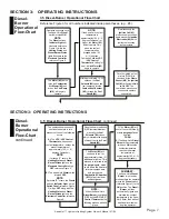
SECTION 3: OPERATING INSTRUCTIONS
Diesel-
Burner
Operational
Flow-Chart
NOTE:
If the Aqua-Hot’s coolant
temperature is
approximately 190 (+/- 5)
degrees Fahrenheit, or
higher, the
Motor (#2)
will not operate. Only
when the coolant
temperature has
dropped below 160
(+/- 5) degrees
Fahrenheit, and the
VDC
/ VAC Control
Thermostat
is calling for
heat, will the
Motor (#2)
begin to operate
.
Operation sequence once
the Aqua-Hot’s
Diesel
switch is turned
ON
.
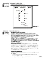
NOTE:
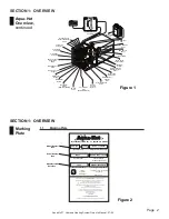
The
Diesel
switch’s
Indicator Light
will
illuminate (reference
Figure 3), while the
Heating Status
and
Diesel-Burner Status
lights illuminate on the
Electronic Controller
,
reference Figure 6
.
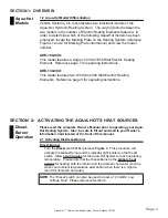
The
Motor (#2)
, which
turns the
Combustion
Air Blower (#5)
and
drives the
Fuel Pump
(#14)
, will begin to
operate.
After approximately 10 - 25
seconds, the
Fuel
Solenoid (#6)
opens and
fuel is sprayed into the
Combustion Chamber
(#11)
through the
Fuel
Nozzle (#9)
.
Once the ignited air-fuel
mixture (FLAME) is
observed by the
Flame
Sensor (#13)
, the
Ignition
Coil (#3)
will automatically
switch
OFF
. The
combustion process now
continues to operate
unassisted.
Simultaneously the
Ignition Coil (#3)
produces a high voltage
spark across the
Ignition
Electrodes (#8),
which
ignites the incoming
air-fuel mixture
.
3.5 Diesel-Burner Operational Flow-Chart
Reference Figure 3 for all numbers indicated inside parentheses. (e.g., #8).
SECTION 3: OPERATING INSTRUCTIONS
The combustion process will
continue to operate in this
manner until one of the following
occurs:
A.)
The
VDC / VAC Control
Thermostat
, which senses
coolant temperature, reaches the
preset temperature of
approximately 190 (+/- 5)
degrees Fahrenheit
.
NOTE:
If process "A" occurs, the
Heating Status
and
Diesel-
Burner Status
lights on the
Electronic Controller
will go
OFF
, reference Figure 6.
B.)
The Aqua-Hot’s
Diesel
switch
is turned
OFF
.
NOTE:
If process "B" occurs, the
Diesel
switch’s
Indicator Light
, on the
Switch Panel
(reference Figure
3), will go
OFF
along with the
Heating Status
and
Diesel-
Burner Status
lights on the
Electronic Controller
, reference
Figure 6.
SUMMARY:
The Aqua-Hot’s
Diesel-
Burner
is in stand-by
mode anytime the operator
moves the
Diesel
switch
(reference Figure 3) to the
ON
position. The
Diesel-
Burner
will then
automatically ignite and
maintain the coolant
temperature in the Aqua-
Hot’s Boiler Tank without
additional involvement
from the operator.
1.)
The
Motor (#2)
will
shut-off once the three (3)
minute
purge-cycle
has
expired.
-THEN-
2.)
The Aqua-Hot’s
Diesel-
Burner
will automatically
turn back
ON
once the
coolant temperature
reaches the preset
temperature of
approximately 160 (+/- 5)
degrees Fahrenheit.
The
Motor (#2)
will
continue to run for
approximately three (3)
additional minutes. This
process is referred to as
the
purge-cycle
, which
cools down the heater’s
internal components
and purges the
Combustion Chamber
(#11)
of any residual
exhaust gases.
Once the heater switches
OFF
, thermostatically or
manually, the
Fuel
Solenoid (#6)
closes,
which interrupts the supply
of diesel fuel to the
Fuel
Nozzle (#9)
.
NOTE:
When the Aqua-Hot’s
Diesel-Burner
is switched
OFF
, by the
VDC / VAC
Control Thermostat
, the
following process will take
place:
3.5 Diesel-Burner Operational Flow-Chart
, continued
Diesel-
Burner
Operational
Flow-Chart
,
continued
SECTION 3: OPERATING INSTRUCTIONS