17
5 Connecting to power supply
VEGAVIB 61 • Two-wire 8/16 mA
29268-EN-170315
5
5
5
5
1
2
4
3
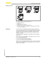
Fig. 9: Material versions, single chamber housing
1 Plastic (not with Ex d)
2 Aluminium
3 Stainless steel (not with Ex d)
4 Stainless steel, electropolished (not with Ex d)
5 Filter element for pressure compensation or blind plug with version IP 66/
IP 68, 1 bar (not with Ex d)
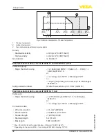
For connection to a VEGATOR (Ex) signal conditioning instrument.
The sensor is powered by the connected VEGATOR signal condition-
ing instrument. Further information is available in chapter "
Techni-
cal data
", "
Ex-technical data
" are available in the supplied "
Safety
information manual
".
The wiring example is applicable for all suitable signal conditioning
instruments.
If the mode switch of VEGAVIB 61 is correctly set to "max.", the con-
trol lamp on VEGAVIB 61 lights.
•
red - with submerged vibrating element
•
green - with uncovered vibrating element
Take note of the operating instructions manual of the signal condition-
ing instrument. Suitable signal conditioning instruments are listed in
chapter "
Technical data
".
Housing overview
Wiring plan


