3
-
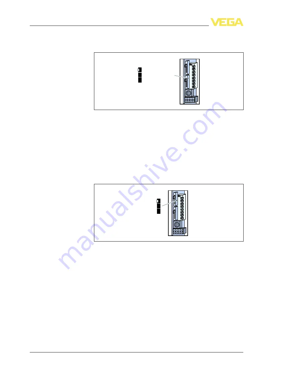
step switch for mode adjustment of the second output relay
.
T
he
individual switch positions are assigned as follows
:
1
2
3
4
5
6
7
8
O
N
3
1
3362
CH1 output parallel
CH2 output separate
CH1 with alarm
F
ig
.
16
:
S
lide switch for adjustment of the relay outputs
(
D
)
l
CH
1
output parallel
-
B
oth relay outputs switch in parallel
.
T
he
second relay
(
15
-
17
)
switches analogue to relay
1
(
4
-
6
)
l
CH
2
output separate
-
T
wo
-
point control or two independent relay
outputs
.
T
he second relay
(
15
-
17
)
switches independently of
relay
1
(
4
-
6
)
l
CH
1
with alarm
-
F
ault signal with relay output
2
.
T
he second relay
(
4
-
6
)
triggers a fault signal
.
3
-
step switch for adjustment of the switching delay
.
T
he adjusted
switching delay applies to the switch on and switch o
ff
delay
.
O
N
3
1
3362
6 s
3 s
0,5 s
1
2
3
4
5
6
7
8
F
ig
.
17
:
S
lide switch for setting the switching delay
(
E
)
l
6
s
l
3
s
l
0
.
5
s
S
lide switch for adjust
-
ment of the relay out
-
puts
(
D
)
S
lide switch for setting
the switching delay
(
E
)
22
VEGATOR
632
•
S
ignal conditioning instrument
6
A
djustment elements
35243
-
EN
-
120228


