Quick setup guide
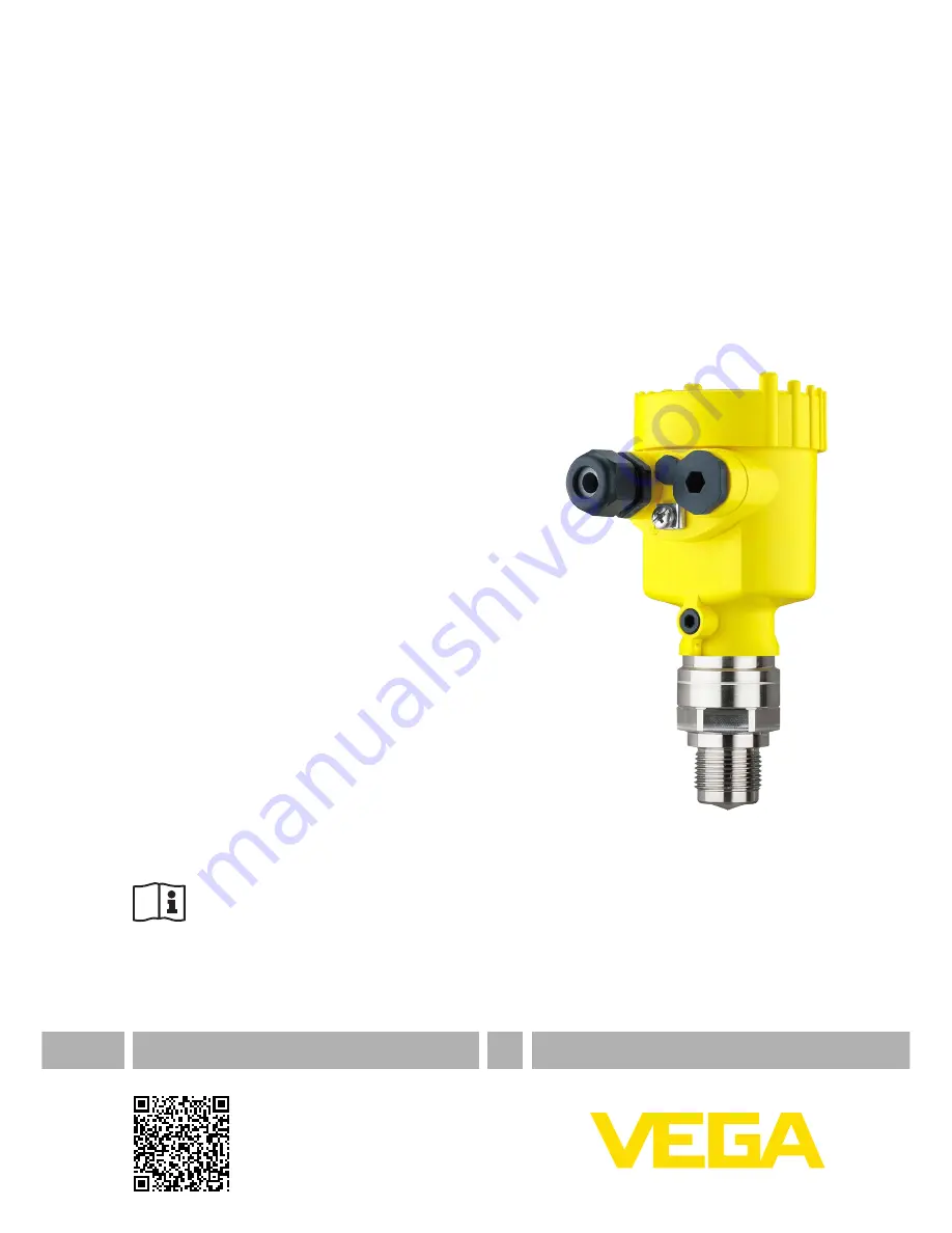
Radar sensor for continuous level
measurement of liquids
VEGAPULS 64
4 … 20 mA/HART - two-wire
Document ID: 51462
Page 1: ...Quick setup guide Radar sensor for continuous level measurement of liquids VEGAPULS 64 4 20 mA HART two wire Document ID 51462...
Page 2: ...housing 10 5 Set up with the display and adjustment module 5 1 Insert display and adjustment module 12 5 2 Parameter adjustment Quick setup 13 5 3 Parameter adjustment Extended adjustment 15 6 Supple...
Page 3: ...tions This is a state of the art instrument complying with all prevailing regulations and guidelines The instrument must only be operated in a technically flawless and reliable condition The operator...
Page 4: ...302372 1 2 V1 2 1 2011 02 for use in closed vessels For operation inside of closed vessels the following conditions must be fulfilled The instrument must be permanently mounted on a closed vessel made...
Page 5: ...safety VEGAPULS 64 4 20 mA HART two wire 51462 EN 160111 Please help us fulfill this obligation by observing the environmental instructions in this manual Chapter Packaging transport and storage Chap...
Page 6: ...12 Reminder to observe the instrument documentation The type label contains the serial number of the instrument With it you can find the following instrument data on our homepage Product code HTML Del...
Page 7: ...clination in steps 2 For angle of inclination infinitely variable Depending on the selected variant the sensor can be rotated in the strap Single chamber housing Angle of inclination in three steps 0...
Page 8: ...ese can be suppressed by an appropriate adjustment see chapter Setup If you cannot maintain this distance you should carry out a false signal storage during setup This applies particularly if buildup...
Page 9: ...s To do this lift the terminal block with a small screwdriver and pull it out When reinserting the terminal block you should hear it snap in Proceed as follows 1 Unscrew the housing lid 2 If a display...
Page 10: ...eased the terminal closes again You can find further information on the max wire cross section under Technical data Electromechanical data 7 Check the hold of the wires in the terminals by lightly pul...
Page 11: ...mA 2 3 4 1 Fig 8 Electronics and terminal compartment single chamber housing 1 Voltage supply signal output 2 For display and adjustment module or interface adapter 3 For external display and adjustme...
Page 12: ...ed by 90 It is not necessary to interrupt the power supply Proceed as follows 1 Unscrew the housing lid 2 Place the display and adjustment module on the electronics in the desired position and turn it...
Page 13: ...her lid with an inspection glass is required 5 2 Parameter adjustment Quick setup To quickly and easily adapt the sensor to the application select the menu item Quick setup in the start graphic on the...
Page 14: ...nu item you enter the height of the vessel and hence the active measuring range 6 Max adjustment In this menu item you carry out the max adjustment Enter the measuring distance for 100 filling 7 Min a...
Page 15: ...ghting Diagnosis Information for example on device status peak value simulation echo curve Additional adjustments Date Time reset copy function scaling current output false signal suppression lineariz...
Page 16: ...djustment is always carried out without changing the product level These settings can be made ahead of time without the instrument having to be installed The function Setup allows the echo curve to be...
Page 17: ...ent Max adjustment 0 000 m d 100 00 Min adjustment 30 m 0 00 Damping Integration time 0 0 s Current output Current output Mode Output characteristics 4 20 mA Reaction when malfunctions occur 3 6 mA Cu...
Page 18: ...caling Scaling size Volume in l Scaling format 0 corresponds to 0 l 100 corresponds to 0 l Current out put 1 Current output Meas vari able Lin percent Level Current output Adjustment 0 100 correspond...
Page 19: ...ed Proceed as follows 1 Select with the menu item False signal suppression and confirm with OK 2 Confirm again with OK 3 Confirm again with OK 4 Confirm again with OK and enter the actual distance fro...
Page 20: ...hes the metrological conditions in the vessel Extend is used to extend an already created false signal suppres sion This is useful if a false signal suppression was carried out with too high a level a...
Page 21: ...anded wire with end sleeve 0 2 1 5 mm AWG 24 16 Voltage supply Operating voltage UB Non Ex instrument 12 35 V DC Ex d instrument 12 35 V DC Ex ia instrument 12 30 V DC Ex d ia instrument 17 35 V DC Op...
Page 22: ...22 Notes VEGAPULS 64 4 20 mA HART two wire 51462 EN 160111...
Page 23: ...23 Notes VEGAPULS 64 4 20 mA HART two wire 51462 EN 160111...
Page 24: ...g scope of delivery application practical use and operat ing conditions of the sensors and processing systems correspond to the information available at the time of printing Subject to change without...