11
6 Setup
External housing • VEGAFLEX 80 series
46802-EN-200212
6.1 Setup
Setup is carried out according to the operating instructions manual of
the respective sensor.
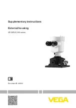
Page 1: ...Supplementary instructions External housing VEGAFLEX 80 series Document ID 46802...
Page 2: ...on 5 3 2 Principle of operation 6 3 3 Storage and transport 6 4 Mounting 7 4 1 General instructions 7 4 2 Mounting preparations 7 4 3 Mounting steps instrument housing 7 4 4 Mounting sensor housing 8...
Page 3: ...ill reach the document download Information note tip This symbol indicates helpful additional infor mation and tips for successful work Note This symbol indicates notes to prevent failures malfunction...
Page 4: ...areas Take note of the Ex specific safety instructions for Ex applications These instructions are attached as documents to each instrument with Ex approval and are part of the operating instructions...
Page 5: ...4 5 Fig 1 Components of the external housing for plics devices N plug A Sensor housing B Instrument housing 1 Screw on cover 2 Base element 3 Housing base 4 Wall mounting plate 5 HF connection cable...
Page 6: ...nciple of operation The external housing is suitable for the following plics sensors VEGAFLEX 81 VEGAFLEX 82 VEGAFLEX 83 VEGAFLEX 86 The external housing cannot be retrofitted 3 3 Storage and transpor...
Page 7: ...g Instrument housing Hexagon socket wrench size 4 Fork wrench wrench size 19 Sensor housing Fork wrench wrench size 8 Fork wrench wrench size 19 We recommend using additional materials when mounting t...
Page 8: ...ic by 180 Turn the cable gland of the electronics housing downward The hous ing can be turned by 330 without the use of any tools Warning With the plastic housing the four screws of the base may only...
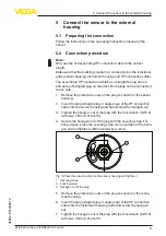
Page 9: ...nnector of the sensor housing 2 Insert the plug straight plug or angle plug of the HF connection cable into the sensor housing and hand screw the hexagon nut 3 Tighten the hexagon nut of the plug with...
Page 10: ...nect the sensor to the external housing External housing VEGAFLEX 80 series 46802 EN 200212 The electrical connection of the electronics module is described in the operating instructions manual of the...
Page 11: ...11 6 Setup External housing VEGAFLEX 80 series 46802 EN 200212 6 Setup 6 1 Setup Setup is carried out according to the operating instructions manual of the respective sensor...
Page 12: ...oing this you help us carry out the repair quickly and without hav ing to call back for needed information If a repair is necessary please proceed as follows Print and fill out one form per instrument...
Page 13: ...ily separable Correct disposal avoids negative effects on humans and the environ ment and ensures recycling of useful raw materials Materials see chapter Technical data If you have no way to dispose o...
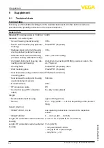
Page 14: ...ing external housing Aluminium die casting AlSi10Mg powder coated Ba sis Polyester Housing base Plastic PBT Polyester 316L Wall mounting plate Plastic PBT Polyester Seal between housing socket and wal...
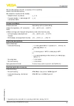
Page 15: ...y and adjustment module 40 80 C 40 176 F With display and adjustment module 20 70 C 4 158 F Electromechanical data Cable entry plug1 Instrument housing 1 x cable gland M20 x 1 5 cable 6 12 mm 2 x blin...
Page 16: ...inless steel with integrated PLICSCOM the housing is 9 mm 0 35 in higher Externes Geh use housing versions 3 2 1 4 69 mm 2 72 79 mm 3 11 117 mm 4 61 M20x1 5 NPT 59 mm 2 32 80 mm 3 15 112 mm 4 41 M20x1...
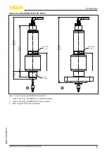
Page 17: ...m 5 43 1 2 3 4 Fig 6 Sensor housing VEGAFLEX 81 1 Sensor housing VEGAFLEX 81 threaded version with cable 2 4 mm 0 079 0 157 in or rod 8 mm 0 315 in 2 Sensor housing VEGAFLEX 81 threaded version with r...
Page 18: ...99 Fig 7 Sensor housing VEGAFLEX 82 1 Sensor housing VEGAFLEX 82 threaded version with cable 4 6 mm 0 157 0 236 in 2 Sensor housing VEGAFLEX 82 threaded version with cable 6 11 mm 0 236 0 433 in or r...
Page 19: ...128 mm 5 04 Fig 8 Sensor housing VEGAFLEX 83 PFA plated 1 Sensor housing VEGAFLEX 83 slotted nut 2 Sensor housing VEGAFLEX 83 Clamp version 3 Sensor housing VEGAFLEX 83 flange version Sensor housing V...
Page 20: ...G1 1 NPT G 1 1 NpT 22 mm 0 87 41 6 mm 1 64 41 6 mm 1 64 51 mm 2 01 29 mm 1 14 50 5 mm 1 99 50 5 mm 1 99 198 mm 7 80 SW 41 mm 220 mm 8 66 Fig 10 Sensor housing VEGAFLEX 86 250 C 1 Sensor housing VEGAFL...
Page 21: ...FLEX 86 280 C 1 2 X G1 1 NPT 35 mm 1 38 45 mm 1 77 258 mm 10 16 308 mm 12 13 SW 60 mm 2 36 X 373 mm 14 69 SW 60 mm 2 36 Fig 11 Sensor housing VEGAFLEX 86 280 C 1 Sensor housing VEGAFLEX 86 threaded ve...
Page 22: ...Sensor housing VEGAFLEX 86 450 C G1 1 NPT 383 mm 15 08 X 447 mm 17 60 35 mm 1 38 45 mm 1 77 X 1 2 Fig 12 Sensor housing VEGAFLEX 86 450 C 1 Sensor housing VEGAFLEX 86 threaded version 2 Sensor housin...
Page 23: ...23 Notes External housing VEGAFLEX 80 series 46802 EN 200212...
Page 24: ...of delivery application practical use and operat ing conditions of the sensors and processing systems correspond to the information available at the time of printing Subject to change without prior n...