13
5 Connecting to power supply
VEGACAP 98 • Relay (DPDT)
33760-EN-230510
2
3 4 5 6 7
+
L1
–
N
8
1
1
2
3
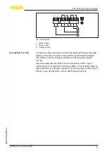
Fig. 5: Wiring plan
1 Relay output
2 Relay output
3 Voltage supply
If inductive loads or stronger currents are switched through, the gold
plating on the relay contact surface will be permanently damaged.
The contact is then no longer suitable for switching low-voltage
circuits.
Inductive loads also result from the connection to a PLC input or
output and/or in combination with long cables. It is imperative that you
take measures to extinguish sparks to protect the relay contact (e.g. Z
diode) or use an electronic version with transistor output.
Connection to a PLC
Summary of Contents for VEGACAP 98
Page 11: ...11 4 Mounting VEGACAP 98 Relay DPDT 33760 EN 230510 Fig 4 Inflowing medium...
Page 28: ...28 Notes VEGACAP 98 Relay DPDT 33760 EN 230510...
Page 29: ...29 Notes VEGACAP 98 Relay DPDT 33760 EN 230510...
Page 30: ...30 Notes VEGACAP 98 Relay DPDT 33760 EN 230510...
Page 31: ...31 Notes VEGACAP 98 Relay DPDT 33760 EN 230510...


