background image

33

Notes

VEGACAP 69 • Two-wire

31177-EN-230510

Summary of Contents for VEGACAP 69

Page 1: ...Operating Instructions Capacitive double rod electrode for level detection VEGACAP 69 Two wire Document ID 31177 ...

Page 2: ...rt and storage 10 3 5 Accessories 10 4 Mounting 11 4 1 General instructions 11 4 2 Mounting instructions 12 5 Connecting to power supply 14 5 1 Preparing the connection 14 5 2 Connection procedure 14 5 3 Wiring plan single chamber housing 15 5 4 Wiring plan version IP66 IP68 1 bar 17 5 5 Warm up reaction 17 6 Setup 18 6 1 General information 18 6 2 Adjustment elements 18 7 Diagnostics and servicin...

Page 3: ...3 Contents VEGACAP 69 Two wire 31177 EN 230510 Editing status 2023 04 26 ...

Page 4: ...s to the Docu ment ID By entering the Document ID on www vega com you will reach the document download Information note tip This symbol indicates helpful additional infor mation and tips for successful work Note This symbol indicates notes to prevent failures malfunctions damage to devices or plants Caution Non observance of the information marked with this symbol may result in personal injury War...

Page 5: ...ect mounting or adjustment Damage to property and persons or environmental contamination can result Also the protective characteristics of the instrument can be impaired 2 4 General safety instructions This is a state of the art instrument complying with all prevailing regulations and directives The instrument must only be operated in a technically flawless and reliable condition The operator is r...

Page 6: ...ly with the relevant requirements of the Canadian Electrical Code CEC Par I Canada 2 7 Safety instructions for Ex areas For applications in explosion proof areas Ex only devices with cor responding Ex approval may be used Observe the Ex specific safety instructions These are an integral part of the operating instructions and are enclosed with every device with Ex approval 2 8 Environmental instruc...

Page 7: ...g instructions manual The respective scope of delivery results from the order specification This operating instructions manual applies to the following instrument versions Hardware from 1 0 0 Software from 1 3 0 Only for instrument versions without SIL qualification The VEGACAP 69 consists of the components Process fitting with probe Housing with electronics Housing cover optionally available with...

Page 8: ...h the serial number you can access the delivery data of the instru ment via www vega com Search You can find the serial number on the inside of the instrument as well as on the type label on the outside The type label contains the serial number of the instrument With it you can find the following instrument data on our homepage Product code HTML Delivery date HTML Order specific instrument feature...

Page 9: ...dielectric constant of the product compared to air the capacitance increases as the material gradually covers the probe The capacitance change is converted by the electronics module into a switching command Depending on your requirements VEGACAP 69 with two wire elec tronics can be connected to different controllers Compatible control lers are listed in chapter Technical data The data for power su...

Page 10: ...left closed and stored according to the orientation and storage markings on the outside Unless otherwise indicated the packages must be stored only under the following conditions Not in the open Dry and dust free Not exposed to corrosive media Protected against solar radiation Avoiding mechanical shock and vibration Storage and transport temperature see chapter Supplement Technical data Ambient co...

Page 11: ...e sensor By doing this you avoid damage to the electronics through inductive coupling Ground the probe before welding directly on the rod or cable Devices with threaded fitting are screwed into the process fitting with a suitable wrench via the hexagon See chapter Dimensions for wrench size Warning The housing or the electrical connection may not be used for screw ing in Depending on the device ve...

Page 12: ...sealing NPT threads it is not possible to have the cable entries screwed in at the factory The free openings for the cable glands are therefore covered with red dust protection caps as transport protection Prior to setup you have to replace these protective caps with ap proved cable glands or close the openings with suitable blind plugs 4 2 Mounting instructions Due to the effects of agitators equ...

Page 13: ...ition in the vessel where no disturbances e g from filling openings agitators etc can occur This applies particularly to instrument versions with a longer probe Fig 5 Inflowing medium The probe should protrude into the vessel to avoid buildup For that reason avoid using mounting bosses for flanges and screwed fittings This applies particularly to use with adhesive products Inflowing medium Nozzle ...

Page 14: ...omagnetic interference is expected which is above the test values of EN 61326 1 for industrial areas shielded cable should be used Make sure that the cable used has the required temperature resist ance and fire safety for max occurring ambient temperature Use cable with round cross section for instruments with housing and cable gland To ensure the seal effect of the cable gland IP protection ratin...

Page 15: ...inals by lightly pulling on them 9 Tighten the compression nut of the cable entry gland The seal ring must completely encircle the cable 10 If necessary carry out a fresh adjustment 11 Screw the housing lid back on The electrical connection is finished 5 3 Wiring plan single chamber housing 1 4 4 4 2 3 Fig 7 Material versions single chamber housing 1 Plastic not with dust Ex 2 Aluminium 3 Stainles...

Page 16: ...ller The sensor is powered by the connect ed controller Further information is available in chapter Technical data Ex technical data are available in the Safety information The wiring example is applicable for all suitable controllers Take note of the operating instructions manual of the controller Suit able controllers are listed in chapter Technical data 1 Fig 9 Wiring plan 1 Voltage supply Elec...

Page 17: ...ly or to the processing system 2 Shielding 5 5 Warm up reaction After connecting to voltage supply or after a voltage recurrence the instrument passes a certain switch on routine By lowering the current value when switching on the instrument can output briefly a fault signal 10 I mA 20 5 2 3 1 5 3 4 5 t s 1 Fig 11 Warm up reaction 1 Measured value Wire assignment con nection cable ...

Page 18: ... mode switch afterwards This could possibly trigger other connected instruments or devices 6 2 Adjustment elements 4 1 2 3 Fig 12 Electronics module Two wire output 1 DIL switch for measuring range selection with compensation button 2 Ground terminal 3 Connection terminals 4 Control lamp A failure can be displayed when the housing is closed only plastic housing Take note of the switching point adj...

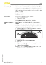
Page 19: ...l of the Controller The adjustment of the switching point is only possible in installed condition Standing capacitances in a vessel can influence the measurement We therefore recommend to carry out a compensation of these stand ing capacitances before the adjustment 1 Make sure that the probe is correctly mounted and connected 2 Make sure that the probe is uncovered 2 1 Fig 13 Compensation key 1 M...

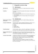
Page 20: ...or Process Voltage supply Signal processing The first measure to take is to check the output signal In many cases the causes can be determined this way and the faults quickly rectified Depending on the reason for the fault and the measures taken the steps described in chapter Setup must be carried out again or must be checked for plausibility and completeness Should these measures not be successfu...

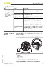
Page 21: ...hen changes the mode the probe may be mechanically damaged Should the switching func tion in the correct mode still be faulty return the probe for repair Check if there is buildup on the probe and if so re move it Unfavourable installation location Check if the probe is covered by buildup on the nozzle Mount the instrument at a location in the vessel where e g no mounds can form Signal lamp flashe...

Page 22: ...Pull out old electronics module 7 Compare the new electronics module with the old one The type label of the electronics module must correspond to that of the old electronics module This applies particularly to instruments used in hazardous areas 8 Compare the settings of the two electronics modules Set the adjustment elements of the new electronics module to the same setting of the old one Informa...

Page 23: ...reen 17 Carry out the adjustment again See chapter Set up adjustment elements 18 Screw the housing lid back on The electronics exchange is now finished 7 4 Shortening of the probe The rod of the probe can be shortened to any length 1 Shorten the rod probe to the requested length with a metal saw 2 Mount the probe into the vessel Make sure that the probe is uncovered 2 1 Fig 17 Compensation key 1 M...

Page 24: ...e By doing this you help us carry out the repair quickly and without having to call back for needed information Proceed as follows in case of repair Print and fill out one form per instrument Clean the instrument and pack it damage proof Attach the completed form and if need be also a safety data sheet outside on the packaging Ask the agency serving you to get the address for the return ship ment ...

Page 25: ...ing to voltage sup ply and carry out the listed steps in reverse order 8 2 Disposal Pass the instrument on to a specialised recycling company and do not use the municipal collecting points Remove any batteries in advance if they can be removed from the device and dispose of them separately If personal data is stored on the old device to be disposed of delete it before disposal If you have no way t...

Page 26: ... Probe double rod fully insulated ø 14 mm 0 551 in 316L Ʋ Ʋ Plastic housing Plastic PBT Polyester Ʋ Ʋ Seal between housing and housing lid Silicone Ʋ Ʋ Ground terminal 316L Ʋ Ʋ Cable gland PA stainless steel brass Ʋ Ʋ Sealing cable gland NBR Ʋ Ʋ Blind plug cable gland PA Process fittings Ʋ Ʋ Flanges DIN from DN 50 ASME from 2 Weight 1 Ʋ Ʋ Instrument weight 0 8 4 kg 0 18 8 82 lbs Ʋ Ʋ Rod weight ø 1...

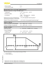
Page 27: ... range 2 Influence of the ambient temperature 0 15 10 K of the adjusted measuring range 3 Ambient conditions Ambient temperature on the housing 40 80 C 40 176 F Storage and transport temperature 40 80 C 40 176 F Process conditions Process pressure 1 2 bar 100 200 kPa 14 5 29 psig Process temperature Ʋ Ʋ Flange of PTFE 40 100 C 40 212 F Ʋ Ʋ Flange of PP 0 60 C 32 140 F 45 C 100 C 1 1 0 2 0 C 40 C 1...

Page 28: ...ng cap NPT Wire cross section spring loaded terminals Ʋ Ʋ Massive wire stranded wire 0 2 2 5 mm AWG 24 14 Ʋ Ʋ Stranded wire with end sleeve 0 2 1 5 mm AWG 24 16 Electromechanical data version IP66 IP68 1 bar Options of the cable entry Ʋ Ʋ Cable entry M20 x 1 5 NPT Ʋ Ʋ Cable gland M20 x 1 5 NPT Ʋ Ʋ Blind plug M20 x 1 5 NPT Ʋ Ʋ Closing cap NPT Connection cable Ʋ Ʋ Wire cross section 0 5 mm AWG 20 Ʋ ...

Page 29: ... precision casting IP66 IP68 0 2 bar IP68 1 bar Type 6P Type 6P Altitude above sea level up to 5000 m 16404 ft Protection class II Functional safety SIL Functional safety according to IEC 61508 IEC 61511 Ʋ Ʋ Single channel architecture 1oo1D up to SIL2 Ʋ Ʋ Multiple channel architecture see supplementary instructions manual Safety Manual SIL Approvals Instruments with approvals can have different t...

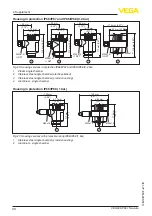
Page 30: ... 5 NPT Fig 20 Housing versions in protection IP66 IP67 and IP66 IP68 0 2 bar 1 Plastic single chamber 2 Stainless steel single chamber electropolished 3 Stainless steel single chamber precision casting 4 Aluminium single chamber Housing in protection IP66 IP68 1 bar 117 mm 4 61 103 mm 4 06 ø 77 mm 3 03 116 mm 4 57 150 mm 5 91 ø 84 mm 3 31 M20x1 5 M20x1 5 M20x1 5 1 2 Fig 21 Housing versions with pr...

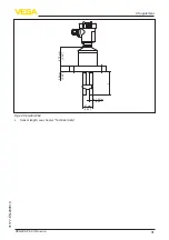
Page 31: ...31 9 Supplement VEGACAP 69 Two wire 31177 EN 230510 ø 14 mm 0 55 47 mm 1 85 L 25 mm 0 98 87 5 mm 3 45 Fig 22 VEGACAP 69 L Sensor length see chapter Technical data ...

Page 32: ... droits de propriété intellec tuelle Pour plus d informations on pourra se référer au site www vega com VEGA lineas de productos están protegidas por los derechos en el campo de la propiedad indus trial Para mayor información revise la pagina web www vega com Линии продукции фирмы ВЕГА защищаются по всему миру правами на интеллектуальную собственность Дальнейшую информацию смотрите на сайте www ve...

Page 33: ...33 Notes VEGACAP 69 Two wire 31177 EN 230510 ...

Page 34: ...34 Notes VEGACAP 69 Two wire 31177 EN 230510 ...

Page 35: ...35 Notes VEGACAP 69 Two wire 31177 EN 230510 ...

Page 36: ...ning scope of delivery application practical use and operat ing conditions of the sensors and processing systems correspond to the information available at the time of printing Subject to change without prior notice VEGA Grieshaber KG Schiltach Germany 2023 Phone 49 7836 50 0 E mail info de vega com www vega com ...

Reviews: