Vega INFO-1 Operating Manual Download Page 21

Vega INFO-1 Operating Manual

Page 21 

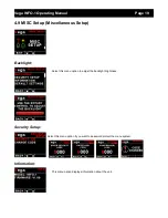
Max Values CRC error. Load default settings to restore to factory defaults. If the error 
message still persists then it could possibly be a non-volatile memory failure in which  
case the instrument will then have to be returned to the factory.

7 Specifications

Operating Temperature Range

-10ºC to 60ºC (14ºF to 140ºF)

Storage Temperature Range

-20ºC to 80ºC (-4ºF to 176ºF)

Humidity

<85% non-condensing

Power Supply

8 to 30Vdc SMPS (switch mode power supply) with built in 33V over 
voltage and reverse voltage protection

Current Consumption

Approx. 73mA @ 13.8V (backlight highest setting), 33mA @13.8V 
(backlight lowest setting)

Display

1.8” 160x128 pixel active matrix TFT display.
1000 cd/m2
Sunlight readable with anti-glare coating
LED Backlight is user configurable

Alarm Output

Open collector transistor switch to ground
Maximum rating 0.25A

ADC

12 bit

Dimensions

see Vega series dimensional drawing

Enclosure

2 1/4” ABS, black in color, front or rear mounting. Flame retardant.

Weight

Approx. 120 grams (Instrument excluding cables)

Non-volatile memory storage

100000 write cycles

Voltage measurement range

Up to 32Vdc

Voltage resolution

0.1V

Current shunts supported

MGL Avionics magnetic field or MGL Avionics active current shunt

G-force range

+-16g typical

OAT Temperature Sender type

Semiconductor LM335 (ON Semiconductor)

Internal battery type

CR2032

8 Operating the alarms

The alarm output can be used to switch an external alarm indicator. The external alarm switch is an open collector
transistor switch to ground with  a maximum rating of 0.25A DC. It is possible to wire the alarm contacts of several
Stratomaster instruments in parallel should this be desired. To avoid false activation of the alarms, the alarm function is
only active 10 seconds after the instrument has powered up.

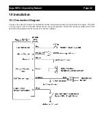
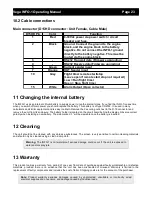
9 Firmware Upgrading

The INFO-1 can  be upgraded in  the  field  by connecting the  RS232 port to a  PC and  running the  firmware  update
program. 

Note that only the RS232 port can be used to upgrade the firmware.

Please see the Vega firmware upgrading document for more information.

Summary of Contents for INFO-1

Page 1: ...Battery Voltage Current and Charge display OAT display Flight Timer Flight log Stopwatch Countdown Timer Alarm Requires the MGL Avionics magnetic field or active current shunt sold separately Vega IN...

Page 2: ...mum voltage reached is also recorded in permanent memory OAT display OAT can be shown in either degrees Celsius or degrees Fahrenheit The INFO 1 also contains a programmable low high OAT alarm The max...

Page 3: ...for harsh electrical environments 1 year limited warranty Requires the MGL Avionics magnetic field or active current shunt sold separately 2 Layout F2 Down Button Menu System Softkey button Normal Dis...

Page 4: ...d and OAT if enabled is shown on all of the main display screens 3 1 UTC Time Display Slip Indicator disabled Slip Indicator OAT disabled Slip Indicator if enabled Local time UTC time OAT display if e...

Page 5: ...timer This push button is only active if the flight timer is set to manual Slip Indicator OAT disabled Flight Timer set for remote start stop Local time G force display Slip Indicator if enabled Loca...

Page 6: ...er screen Use the rotary control to set the countdown timer value Press the F1 key to exit Local time G force display Slip Indicator if enabled Press the F1 key to Start Stop the stopwatch Stopwatch l...

Page 7: ...reen as shown on the left Use the rotary control to set the alarm time Press the F1 key to exit Slip Indicator disabled Slip Indicator OAT disabled Local time Local time label Alarm label Alarm time G...

Page 8: ...l Mode Both battery voltage and current shown Battery discharging Battery charging Battery Voltage only Current measurement disabled Slip Indicator if enabled Local time G force display Local time lab...

Page 9: ...ain displays 3 9 Maximum Minimum Values display Press the F1 key to reset the maximum and minimum values If the security option has been enabled then the correct security code will have to be entered...

Page 10: ...tary control to navigate through the menu system 4 1 Exiting the menu system Press the F1 button to exit the menu system when the EXIT soft key is shown All changes made during navigation of the menu...

Page 11: ...view the next flight log entry Erase Flight Log Use this function to erase the flight log stored in the INFO 1 FT Display Select to enable or disable the flight timer display Flight Select if you wou...

Page 12: ...he negative alarm must be activated Any G force below this value will activate the alarm Pos Cycle Set the positive G force limit above which the cycle counter should increment This would typically be...

Page 13: ...Mean Time GMT or Zulu time UTC Offset Enter the UTC offset for your location The UTC offset can be adjust in half an hour increments UTC Display Select to enable or disable the UTC display SW Display...

Page 14: ...he volts high alarm High Alarm Enter the voltage threshold for when the high alarm must be activated Any voltage above this value will activate the alarm High Caution Enter the voltage for the high ca...

Page 15: ...Alarm Enter the current threshold for when the high alarm must be activated Any current above this value will activate the alarm High Caution Enter the current value for the high caution Low Caution...

Page 16: ...factor until the current is reading correctly It will be best if a multimeter can be inserted in series with the current supplying conductor and the gain calibration adjusted until the INFO 1 matches...

Page 17: ...for the high caution This is the lower value of the upper yellow band Low Caution Enter the temperature for the low caution This is the upper value of the lower yellow band Low Alarm This enables or...

Page 18: ...ivity or a low sensitivity setting Slip Zero This function allows you to set your slip indicator to exactly zero even if your aircraft tends to fly slightly wing down The procedure is to place the air...

Page 19: ...Setup Miscellaneous Setup Backlight Select this menu option to adjust the backlight brightness Security Setup Select this menu option if you want to password protect the menu system Information This m...

Page 20: ...he error message still persists then it could possibly be a non volatile memory failure in which case the instrument will then have to be returned to the factory Internal flash CRC error The instrumen...

Page 21: ...ABS black in color front or rear mounting Flame retardant Weight Approx 120 grams Instrument excluding cables Non volatile memory storage 100000 write cycles Voltage measurement range Up to 32Vdc Volt...

Page 22: ...an external 1A fuse is recommended Connect the supply terminals to your aircrafts power supply The INFO 1 can be used on both 12V and 24V without the use of any pre regulators Ensure that the supply v...

Page 23: ...ar from date of purchase against faulty workmanship or defective materials provided there is no evidence that the unit has been mishandled or misused Warranty is limited to the replacement of faulty c...

Page 24: ...we sell as to your particular application or the compatibility of any of the products we sell with other products you may buy from us or anywhere else and we disclaim any warranties or representation...

Reviews: