background image

F

ig

.

4

:

I

n

owing medium

T

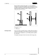
he probe should protrude into the vessel to avoid buildup

.

F

or that

reason

,

avoid using high mounting bosses for screw

-

in

ttings

.

T

his

applies particularly to use in adhesive products

.

M

ake sure that the mechanical connection of the probe to the vessel is

electrically conductive to ensure su

cient grounding

.

U

se conductive seals

,

such as those made of copper or lead

,

etc

.

I

nsulating measures

,

such as covering the thread with

T

e

on tape

,

can

interrupt the necessary electrical connection with metal vessels

.

F

or

this reason

,

ground the probe on the vessel or use a conductive seal

material

.

S

ocket

G

round connection

C

onductive probe

EL

4

11

4

M

ounting

32653

-

EN

-

090415

Summary of Contents for EL 4

Page 1: ...Operating Instructions Conductive probe EL 4 Document ID 32653 Conductive...

Page 2: ...peration 7 3 4 Storage and transport 8 4 Mounting 4 1 General instructions 9 4 2 Mounting instructions 9 5 Connect to power supply 5 1 Prepare the connection 12 5 2 Wiring plan 12 6 Set up 6 1 General...

Page 3: ...d put into practice by them 1 3 Symbolism used Information tip note This symbol indicates helpful additional information Caution If this warning is ignored faults or malfunctions can result Warning If...

Page 4: ...conversions or modi cations are explicitly forbidden 2 3 Warning about misuse Inappropriate or incorrect use of the instrument can give rise to application speci c hazards e g vessel over ll or damag...

Page 5: ...of the environment is one of our most important duties That is why we have introduced an environment management system with the goal of continuously improving company environmental protection The envi...

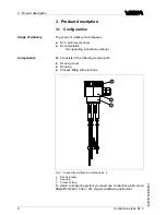
Page 6: ...wing components l Housing cover l Housing l Process tting with electrode 1 2 3 Fig 1 Conductive multiple rod electrode EL 4 1 Housing cover 2 Housing 3 Process tting To create a measuring system you n...

Page 7: ...with EL 4 Conductive probes detect the product resistance when their electro des are covered by the product The switching signal is determined by the length or mounting position of the respective ele...

Page 8: ...completeness and possible transit damage immediately at receipt Ascertained transit damage or concealed defects must be appropriately dealt with Up to the time of installation the packages must be le...

Page 9: ...applies mainly to outdoor mounting as well as installation in areas where high humidity is expected e g through cleaning processes or on cooled or heated vessels Fig 2 Measures against moisture penet...

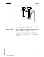
Page 10: ...race or guy directly above the end of the rod 1 2 1 2 Fig 3 Fasten the probe 1 Probe 2 Plastic socket If EL 4 is mounted in the lling stream unwanted false measurement signals can be generated For thi...

Page 11: ...tion of the probe to the vessel is electrically conductive to ensure su cient grounding Use conductive seals such as those made of copper or lead etc Insulating measures such as covering the thread wi...

Page 12: ...operating instructions manual of the corresponding signal conditioning instru ment Line monitoring To realize a line monitoring a resistor of 220 k must be integrated in the connection housing of the...

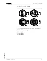
Page 13: ...Connection compartment of the probe 220 k resistance between terminals 1 and 2 1 Connection terminal 1 longest rod 2 Connection terminal 2 shortest rod A Probe with 2 rods B Probe with 3 rods C Probe...

Page 14: ...up 6 1 General information You can nd the setup procedure for EL 4 in the operating instructions manual of the corresponding signal conditioning instrument 14 Conductive probe EL 4 6 Set up 32653 EN 0...

Page 15: ...he English language The service is free of charge only the standard telephone costs will be charged 7 3 Shortening the probe The probe can be shortened by any amount Note Take note when shortening mul...

Page 16: ...y serving you for the address of your return shipment You can nd the respective agency on our website www vega com under Company VEGA worldwide 16 Conductive probe EL 4 7 Maintenance and fault recti c...

Page 17: ...be easily separable WEEE directive 2002 96 EG This instrument is not subject to the WEEE directive 2002 96 EG and the respective national laws Pass the instrument directly on to a specialised recycli...

Page 18: ...with plastic housing 400 g 14 oz Rod weight 4 mm 0 157 in 100 g m 1 1 oz ft Sensor length L1 L5 0 1 4 m 0 328 13 12 ft Insulation length 78 mm 3 in Output variable Suitable signal conditioning instru...

Page 19: ...an have di erent technical data For these instruments the corresponding approval documents have to be taken into account These are part of the delivery or can be downloaded under www vega com via VEGA...

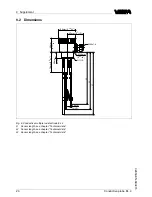
Page 20: ...60mm 2 23 64 G1 A 22mm 55 64 L2 L3 L1 M20x1 5 Fig 6 Conductive multiple rod electrode EL 4 L1 Sensor length see chapter Technical data L2 Sensor length see chapter Technical data L3 Sensor length see...

Page 21: ...es lignes de produits VEGA sont globalement prot g es par des droits de propri t intellectuelle Pour plus d informations on pourra se r f rer au site http www vega com VEGA lineas de productos est n p...

Page 22: ...22 Conductive probe EL 4 9 Supplement 32653 EN 090415...

Page 23: ...Conductive probe EL 4 23 9 Supplement 32653 EN 090415...

Page 24: ...vega com Printing date ISO 9001 All statements concerning scope of delivery application practical use and operating conditions of the sensors and processing systems correspond to the information avail...

Reviews: