background image

Vega VLB-44 Lantern 


25 Jan 2011 - Rev 9 


Programming – Reading a Program Setting 

 
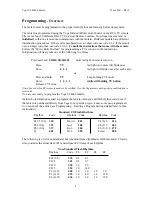
The program settings can be deciphered by reading and recording (writing down) lantern flash 
sequences upon activation with the IR remote control.  The flash rhythm and intensity are read as 
separate sequences and may be used to verify the setting(s) without reprogramming the lantern.  
To check a program setting, power the lantern from a 12 VDC source in daytime conditions, aim 
the programmer at the window above the label and enter the following codes: 
 
To check flash rhythm:   


To check intensity setting: 


          Code 


             Code 

Operation 

Read Settings   

9  

Operation 

Read Settings   

   9 

Feature  

Flash Rhythm   

0  

Feature  

Intensity Setting (night)    1  or 

      Feature 

 Intensity 

Setting 

(day) 


To check LED version: 


          Code 

Operation System 

Check 

  3 

Feature  

LED Version 


5   (for example, will display 

421

 as a series of flashes)


For example, to check if a lantern is programmed as a FL4(.4), look up the code on page 3 (code 
321): 

1.


Press and hold the 
standby/program/power button for 5 
seconds. 

 
2.


Enter the programming sequence to 
determine the flash rhythm: 

90

 (wait 

for confirmation flash after each 
digit). 

 The sequence to determine 

intensity is 91 and the sequence to 
determine the LED version is 35. 


3.


Leave the programmer idle for 10 
seconds. 

The lantern will give 4 quick flashes to 
indicate that it has entered the programming 
mode. 
 
The lantern will flash once each time a key 
on the programmer is pressed.  When the 
sequence is entered and accepted, the lantern 
will display the value 

321

 as a series of 

flashes as: 3 quick flashes followed by a 0.5 
sec gap, 2 quick flashes followed by a 0.5 
gap, 1 quick flash. 
 
The lantern will display 2 quick flashes, a 
pause followed by 2 quick flashes, display 
the FL4(.4) rhythm for 16-20 seconds, then 
turn off (if daytime). 
 

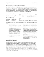
Custom Flash Rhythms 


For flash rhythms not listed in this manual or in the Vega IR Programming manual, a custom 
rhythm can be programmed into the lantern.  The programming sequence has the following 
limitations: the minimum flash and eclipse is 0.1 seconds (generally not a problem with CG 
rhythms), the ADD code must be used for flash and eclipse lengths that exceed 12.75 seconds. 
 
The programming sequence consists of 3-digit codes representing the flash and eclipse intervals.  
Each 3-digit code is a multiple of 0.05 seconds.  As an example, a 1 second flash is equal to a 
code of 1/0.05 = 20 or code 020.  A 9.5 second eclipse is equal to 9.5/0.05=190 or code 190.  An 
eclipse of 15 seconds has to be entered as two codes (split in half for simplicity), so 7.5/0.05=150 
using the ADD code (explained later). 

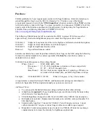
Summary of Contents for VLB-44

Page 1: ...evel This regulates the 2 5 degree lantern to lighthouses or rock solid structures unaffected by wind or waves The VLB 44 is available with up to 8 tiers of LEDs to increase intensity This lantern req...

Page 2: ...tern with the fewest number of tiers LED Version The capabilities of LEDs change rapidly Periodically Vega uses new LEDs in a specific lantern or group of lanterns This impacts the lantern s intensity...

Page 3: ...contract specialist if the Item No listed in the contract is included with your order VLB 44 Color Divergence Tiers Base Mount Where Color WHT RED GRN YEL Divergence 2 5 05 10 for lighthouses structur...

Page 4: ...Press and hold TV keep holding TV button Enter 1 0 6 2 while still holding TV button Release TV button Note the codes for RCA remote needs to be verified Use the Vega remote until positive confirmatio...

Page 5: ...he Light List It is not practical to flash the VLB 44 at a 0 1 second rate A typical rhythm would be 1s FL 4s EC 1s FL 9s EC Note that the period remains the same 15 seconds and the duty cycle is 2s 1...

Page 6: ...night and intensity set for both day and night The daylight control function is performed by the SACII III and the lantern is controlled by power being applied at dusk and secured at dawn by the SACI...

Page 7: ...ds 2 Enter the programming sequence for the flash rhythm 10337 wait for confirmation flash after each digit 3 Leave the programmer idle for 10 seconds to exit the programming mode The lantern will giv...

Page 8: ...presenting zero 0 The light will give 2 quick flashes followed by a short pause then another 2 quick flashes After this it will flash on the programmed rhythm at the selected intensity for 16 20 secon...

Page 9: ...to determine the LED version is 35 3 Leave the programmer idle for 10 seconds The lantern will give 4 quick flashes to indicate that it has entered the programming mode The lantern will flash once ea...

Page 10: ...or 020 For the 4 second eclipse the code is 4 0 05 80 or 080 The 14 second eclipse exceeds the 12 75 second limitation so it is entered as two 7 second codes 7 0 05 140 The ADD code is 001 000 is the...

Page 11: ...ep 2 Try the code again or wait at least 10 seconds to exit the programming mode and reenter the above sequence step 1 Bench Test Bench test each beacon with a 12 volt DC power source to ensure proper...

Page 12: ...viewed at low heights of eye 4 8 A 9 3 No of Tiers A 1 4 4 2 5 9 3 7 5 4 9 1 5 10 7 6 12 2 7 13 8 8 15 4 For high base add 2 8 to A dimension 2 5 degree lantern is 10 9 Mount 3 holes On a 7 7 8 bolt c...

Page 13: ...n Replacements are available from COMDT CG 432A Screw the four bird spikes into the top of the lantern Install the appropriate solar panel using the solar panel installation kit and the appropriate nu...

Page 14: ...ositive and white or blue for negative The green yellow wire is a sync wire and is only used to synchronize two lanterns together DO NOT connect it to the buoy hull The box is gray and may be painted...

Page 15: ...s outlined in the Short Range Aids to Navigation Servicing Guide Be sure the tilt angle is appropriate for the area and that the panel is facing south The leads from the lantern and solar panel should...

Page 16: ...rent of the VLB 44 is below 1 5 amps see the programming section for additional info regarding the daylight control and daytime intensity setting Technical Data Sheet 96 03 http www uscg mil hq cg4 cg...

Page 17: ...r stripping back the appropriate length of outer jacket and conductor jacket tin the ends of the wire with rosin core solder Slide a long piece of heat shrink tube on each conductor and crimp and sold...

Page 18: ...r Blue Note how ends are sealed with heat shrink Green Yellow not used Only used when double stacking 8 tier lanterns For most applications a 2 wire power cable will suffice Questions Comments Questio...

Reviews: