background image


Vega SI-21 / User Manual 


Revision 11 – 23 October 2020  


12 

INITIAL STARTUP 

Vega SI-21 pulse counter is constantly on but can operate in a special "Storage" mode, 

designed for storage and transportation. The device does not regularly transmit data to the 
network in this mode. Before use switch the counter from the «Storage» mode. 

Vega SI-21 supports two activation methods in the LoRaWAN network - ABP and OTAA. 

Select one of the methods using the «Vega LoRaWAN Configurator» application (see part 4).  

1.  ABP.  After pressing the start button, the device immediately starts working in the 

"Active" mode.  

2. OTAA. After pressing the start button, the device makes three attempts to connect to 

the network within the set  frequency  plan.  After  the activation in the LoRaWAN network is 
confirmed, the device sends a signal (LED flashing for 3 seconds) and switches to the "Active" 
mode.  If all attempts fail, the counter will continue to accumulate data and will attempt to 
connect to the network every 6 hours. 

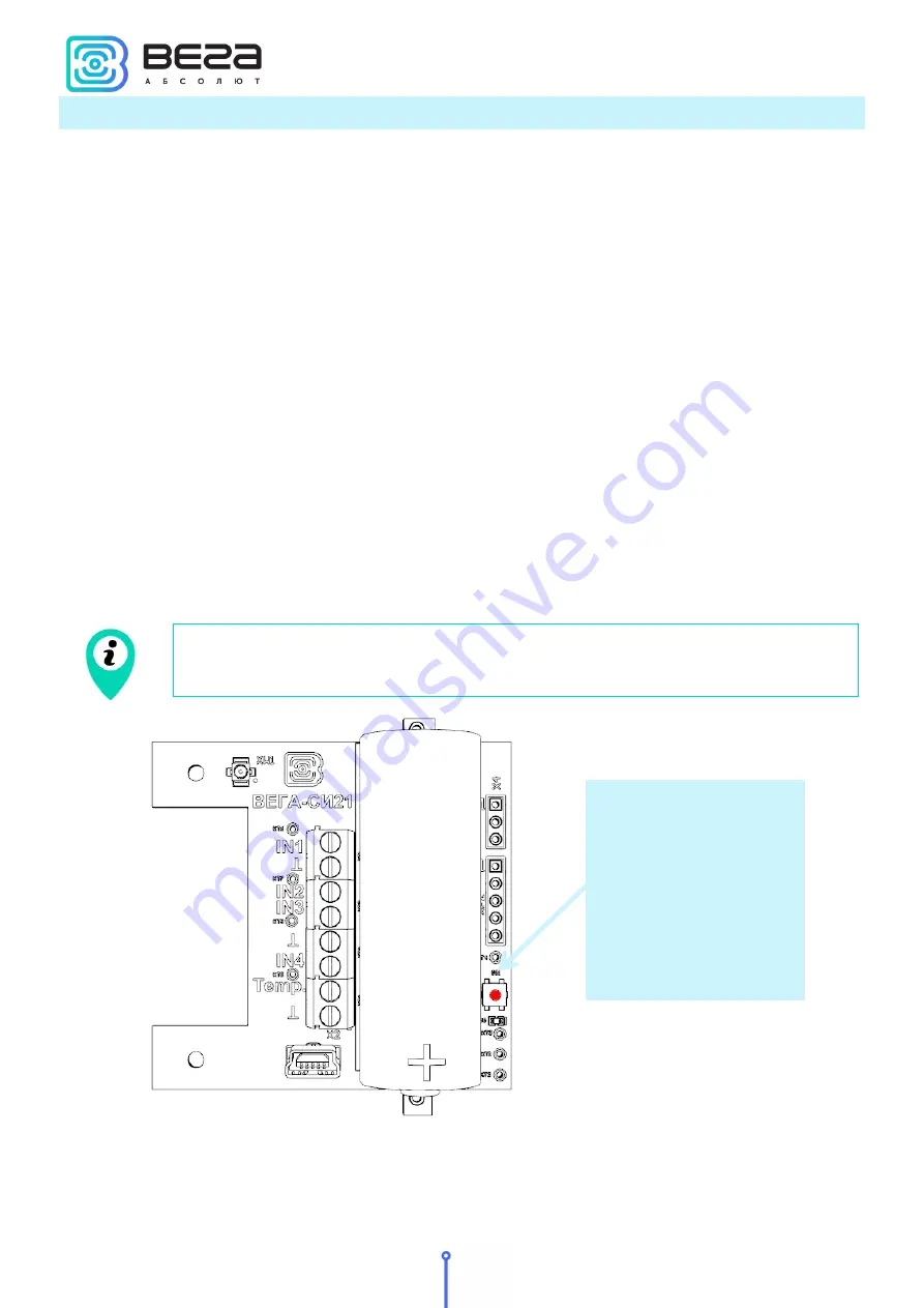
Hold the start button pressed (min. 5 seconds)  to switch the device from the "Active" 

mode back to the "Storage" mode. 


When switching to the "Storage" mode, all readings  from the pulse inputs 
accumulated in the device memory are reset 


Push start button 

on the board  

Summary of Contents for VEGA SI-21

Page 1: ...Vega SI 21 is used for reading of values from metering instruments such as water and electricity meters and further transmitting of this data to LoRaWAN network Vega SI 21 can be used as a security d...

Page 2: ...s 05 24 07 2018 KEV Added frequency plans changes in the communication protocol in technical characteristics 06 28 08 2018 PKP KEV Protocol changed Timestamp added to alarm packet Pulse input scheme i...

Page 3: ...itial Startup 12 Connecting via USB 13 4 VEGA LORAWAN CONFIGURATOR 15 Interface of the application 15 Connection to the device 16 Device info tab 18 LoRaWAN settings tab 20 Vega SI 21 tab 24 5 COMMUNI...

Page 4: ...pecialists familiar with installation work fundamentals of electronic and electrical equipment To provide the stable radio between the gateway and the end device it is recommend avoiding the device in...

Page 5: ...an extraordinary communication session The data collection period for operation within the temperature range and outside is configurable separately The pulse counter can be used for any utilities met...

Page 6: ...lection period for the case when the measured temperature values go out the specified temperature range With the Confirmed uplinks option turned on the device will send the next packet only after rece...

Page 7: ...ernal clock o Communication in case of security inputs actuation o Charge measuring of the built in battery MARKING Device marked with sticker that contain the next information o Device model o DevEUI...

Page 8: ...AS923 AU915 KR920 US915 KZ865 custom EU868 based Activation type ABP or OTAA Communication period 5 15 30 minutes 1 6 12 or 24 hours Data collection period 5 15 30 minutes 1 6 12 or 24 hours Memory am...

Page 9: ...not supported Polarity effects only open collector circuits Pulse inputs can be configured for work in the Security mode via the Vega LoRaWAN Configurator application In this mode the device does not...

Page 10: ...ober 2020 10 Also there are a couple of contacts on the board for connection an external thermistor it is contacts Temp and It is necessary to configure sending parameters for thermistor readings in t...

Page 11: ...e changed LED signal Meaning Series of short flashings Linking to the network One long flashing The device connected to the network and is in active mode Three long flashings Linking to the network is...

Page 12: ...button the device immediately starts working in the Active mode 2 OTAA After pressing the start button the device makes three attempts to connect to the network within the set frequency plan After th...

Page 13: ...RaWAN Configurator application See part 4 Before connecting the device to the computer for the first time you must install the driver for the COM port stsw stm32102 which can be downloading from iotve...

Page 14: ...indow you need to click Next then Install and then the installation will begin When the installation is completed successfully the following screen appears After pressing Finish the driver is ready fo...

Page 15: ...mode the basic settings advanced settings and the ability to check the coverage area of the signal from the gateways are available Next the work of the application considering in the Expert mode INTE...

Page 16: ...gs in the device memory respectively The application window contains three tabs Device info LoRaWAN settings and device settings The language selection menu is in the upper right corner CONNECTION TO...

Page 17: ...d to click the Get settings button until this point the application will display the default settings or from the last connected device After making the necessary changes to the settings you should cl...

Page 18: ...reset the keys back to the factory settings Device info the configurator reads information about the device model its firmware and protocol version also automatically corrects the device s time when c...

Page 19: ...ial signal to the LoRaWAN network in response to which the network informs it of the number of gateways that received this signal and the signal quality This button only works when the device is conne...

Page 20: ...68 based In the device frequency plan only those channels are active by default on which sending requests for connection to the network join channels The remaining channels that the device should use...

Page 21: ...firmation or until the Uplink number of transmission is over see below If you choose to send a packet without confirmation the modem will not know whether the packet is delivered or not ADR this optio...

Page 22: ...twork while OTAA mode active The second window always opens after 1 second after the first Uplink number of transmission not displayed in the Simple mode if the Confirmed uplinks function is disabled...

Page 23: ...adjusted to this value when sending packets to the LoRaWAN network This option can be changed by the network server TX datarate not displayed in the Simple mode the device transmission datarate at whi...

Page 24: ...the pulse count at the inputs it is necessary to put the device in the Storage mode by pressing the button on the board for a long time more than 5 seconds see section Initial startup Input settings...

Page 25: ...ata collection period is set to 24 hours at 00 00 and at 12 00 if the period is 12 hours and so on All readings are stored in the device memory until the next communication session The data transfer p...

Page 26: ...Input 3 reading depending on the type number of pulses or status 0 open 1 closed uint32 4 bytes Input 4 reading depending on the type number of pulses or status 0 open 1 closed uint32 1 byte Temperatu...

Page 27: ...type this packet 255 4 bytes Time of the modem at moment of the packet transmission unixtime UTC After receiving this type of package the application can send to modem the packet with time correction...

Page 28: ...vice Size in bytes Field description Data type 1 byte Packet type this packet 0 uint8 2 bytes ID of parameter uint16 1 byte Data length len uint8 len bytes Parameter value 2 bytes ID of parameter uint...

Page 29: ...24 hours 5 5 minutes 6 15 minutes 7 30 minutes 55 Time zone in minutes 2 bytes from 720 to 840 78 Data collection period when temperature is out of the thresholds 1 byte 1 1 hour 2 6 hours 3 12 hours...

Page 30: ...ON REQUIREMENTS Vega SI 21 pulse counter shall be stored in the original packaging in heated room at temperatures 5 to 40 and relative humidity less than 85 The counter shall be transported in covered...

Page 31: ...ser Manual Revision 11 23 October 2020 31 7 CONTENT OF THE PACKAGE The pulse counter is delivered complete with Vega SI 21 pulse counter 1 pc LoRaWAN antenna 1 pc External thermistor 1 pc Factory cert...

Page 32: ...pecified in this user manual Warranty does not apply to power supplies of devices sending more than 80 000 packets the device with mechanical electrical and or other damages and defects caused by viol...

Page 33: ...Vega SI 21 User Manual Revision 11 23 October 2020 33 vega absolute ru User Manual Vega Absolute OOO 2017 2020...

Reviews: