background image

6-1

6  

Checking the System 

Setting the Signal Strength Jumper

IMPORTANT! You must install the WPLLD transducer prior to performing this procedure. 

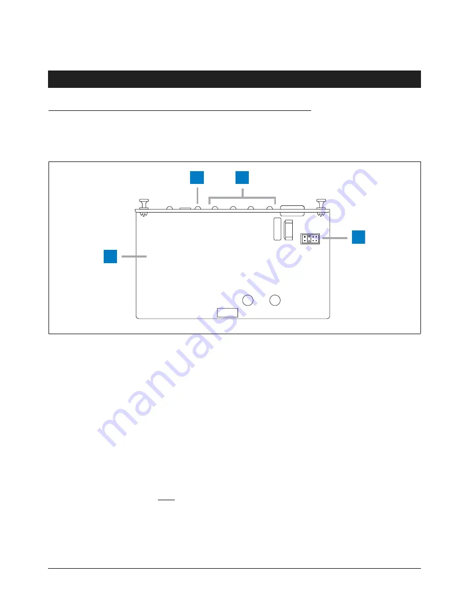
To obtain optimum signal reception from the transducer, it may be necessary to change the noise/signal strength jumper 
position (see Figure 6-1). The default position is R98.

Figure 6-1.   Noise/Signal Strength Jumper Settings

GUIDELINES

1. For optimum data reception, the LEDs on the front of the WPLLD AC Interface Module should turn On as follows.

a. When a WPLLD transducer is not transmitting:

None of the 4 red LEDs should be lit (indicating no noise on the line). One dimly flashing red LED is acceptable; 
however, if more than 1 of the red LEDs are flashing, you have excessive noise on the ac line and it should be 
removed before continuing. Start turning off electrical signs, motors, etc., one item at a time, until the noise is 
eliminated. Replace the device causing the noisy condition.

R101 R98  R96 R93

wplld/acunder.eps

1

2

3

4

Legend for numbered boxes in Figure 6-1:

1

Underside of WPLLD AC Interface Module.

2

Green XMIT LED - flashes when information is received from a WPLLD transducer. 

3

Number of LEDs lit indicate signal strength received from WPLLD transducers. At least 3 LEDs 
should be lit, when receiving transducer communications, indicating good signal strength.

4

Noise/signal strength jumper settings. R98 is default setting.

Summary of Contents for WPLLD

Page 1: ...WPLLD Manual No 576013 923 Revision V Site Prep and Installation Guide...

Page 2: ...all components and units as soon as they are received If damaged write a complete and detailed description of the damage on the face of the freight bill The carrier s agent must verify the inspection...

Page 3: ...antum and The Red Jacket 4 1 SwiftCheck Valve Installation 4 1 Adjusting the Pressurstat Relief Pressure for 3 0 gph testing only 4 3 Disabling the Functional Element required for 0 2 0 1 gph testing...

Page 4: ...Pump 4 10 Figure 4 13 Wiring the WPLLD Transducer to the FE Petro Pump 4 11 Figure 4 14 WPLLD Transducer Installation FE Petro Pump 4 12 Figure 4 15 Manifolded Product Lines WPLLD Installation Dual Pu...

Page 5: ...may only be submitted by selected Distributors Related Manuals 576013 879 TLS 3XX Series Site Prep and Installation Manual 577013 465 Line Leak Application Guide 577013 481 WPLLD Modules Installation...

Page 6: ...l not detect leaks less than 3 0 gph In this situation the system will always pass 0 2 and 0 1 gph tests but the results will not be valid 4 Ensure that the submersible pump is properly grounded per t...

Page 7: ...0020 416 And Interlock Relay Non Vented Swift Check Valve for Secondary pump V R Kit P N 330020 416 Red Jacket Pressurstat TM Assy P Ns 323 006 5 323 001 5 323 007 5 AG or 323 002 5 AG 849490 003 Not...

Page 8: ...ion Guide 576013 923 1 O ring Line Leak Sensor 512700 225 1 Label 331058 001 1The 849490 004 systems require that a SwiftCheck Valve be purchased separately Contained in Red Jacket Install Kit 330020...

Page 9: ...crews 510500 457 1 Label 331058 001 Contained in Install Kit 330020 412 Table 1 6 WPLLD System 849490 006 Quantity Description Part Number 1 Wireless Line Leak Sensor 331474 015 1 Sensing Line 410138...

Page 10: ...system isolate the inactive lines from the active lines using a shutoff valve Failure to do so may cause inaccurate leak test results Existing Check Valves You must ensure that there are no existing c...

Page 11: ...ing for multiple pump controls may be entering the console through the same conduit open ing be sure to color code or mark each wire to identify its source WPLLD AC Interface Module 1 Turn Off tag and...

Page 12: ...ation Excessive noise will cause WPLLD Comm alarms resulting in line shutdowns Verification is done as follows 1 Turn On all electrical equipment at the site and leave it on during this entire procedu...

Page 13: ...e extension jacks If unplugging one of these devices causes the LED to go off that device is not compatible with WPLLD and should not be used IMPORTANT Do not unplug equipment required for site operat...

Page 14: ...ector LLD remove the mechanical unit and any related tubing and fittings Plug any tubing openings using appropriate fittings and seal using a UL classified thread sealant suitable for the fuel involve...

Page 15: ...stall the WPLLD valve Figure 4 2 in the Mechanical LLD pump port IMPORTANT Do not overtighten the valve when installing into the pump Overtightening the valve can cause it to stick resulting in a flow...

Page 16: ...Replace the brass cap you only have to hand tighten it because the O ring completes the seal Figure 4 3 Pressurstat Adjustable Check Valve DISABLING THE FUNCTIONAL ELEMENT REQUIRED FOR 0 2 0 1 GPH TE...

Page 17: ...ith a UL classified nontoxic thread sealant suitable for the fuel involved Do not apply sealant to the threads adjacent to the flare fitting 3 Remove the O ring from the installation kit and lightly l...

Page 18: ...D transducer Figure 4 5 Wiring the WPLLD Transducer to the Pump 6 Place the shield from the installation kit into the capacitor housing with open side up Hold the shield at an angle and place notched...

Page 19: ...he two 6 32 x 0 375 screws provided attach the capacitor cover bracket to the top of the transducer Snap the capacitor cover into the storage bracket Figure 4 7 WPLLD Transducer Installation Red Jacke...

Page 20: ...rning Tag Line Test Port W ARNING THE SUBM ERGED PUM P SYSTEM SUPPLYIN G THE DIS PENSERS M AY TURN ON UNEXPECTEDLY TO PERFORM A LIN E LEAK TEST THIS M AY RESULT IN FUEL SPRAYIN G DURIN G DIS PENSER PR...

Page 21: ...tion in Red Jacket Quantum Pump WARNING DO NOT APPLY ANY THREAD SEALANT OR PIPE DOPE TO THE THREADS OF THE WPLLD TRANSDUCER OR TO THE THREADS OF THE STP S MOTOR CAPACITOR WELL INTO WHICH IT IS SCREWED...

Page 22: ...THREADS OF THE WPLLD TRANSDUCER OR TO THE THREADS OF THE STP S MOTOR CAPACITOR WELL INTO WHICH IT IS SCREWED The metal to metal joint created by threads of the WPLLD transducer in the STP s capacitor...

Page 23: ...ALLATION 1 Turn Off tag and lockout power to pump 2 Remove the plug from the top of the Pressure Test Port and adjust Valve Clamp if necessary Figure 4 14 3 For precision testing install the FE Petro...

Page 24: ...13 Using the electrical connector provided connect the 2 cut black leads to either one of the wires from the WPLLD transducer Figure 4 13 Wiring the WPLLD Transducer to the FE Petro Pump 8 Cut the or...

Page 25: ...pump is energized only when dispensing but is turned Off when performing line tests Refer to page 5 1 for specific installation instructions A non vented SwiftCheck valve must be installed in the sec...

Page 26: ...stalled in the secondary pump s Dielectric unions and flexible piping elements should be used as required by federal state and local requirements for the specific piping application Location of unions...

Page 27: ...nitored containment sump or mechanical leak detector is required The WPLLD will not detect leaks upstream from the valve i e between the valve and the Submersible Pump Also there must not be a check v...

Page 28: ...sor Containment sump SwiftCheck valve Flexible fuel line Note Remove in line check valve if present Healy Mini Jet TM Product line to dispensers Red Jacket leak detector fitting Red Jacket Part No 038...

Page 29: ...able to start the submersible pump to perform a line leak test and shut the pump off if a leak is detected To enable this feature interrupt the AC Line between the Dispenser ON Switch and the pump con...

Page 30: ...Connect a wire from the C terminal on the 4 Relay output or I O Combination module into the wire connecting the L1 terminal on the WPLLD Controller Module to 120 volt AC line 7 If installing a system...

Page 31: ...Control Box PI 1 PR LI PO PI 2 PR LI PO PI 3 PR LI PO RELAY RATINGS FORM A CONTACTS 120 or 240 VAC 2A MAX WIRELESS PRESSURE LINE LEAK CONTROLLER MODULE Pump Contactor 120 or 240 Vac Line 15 Amp Max A...

Page 32: ...TROLLER MODULE PI PR L1 PO PI PR L1 PO PI PR L1 PO 1 2 3 PUMP INPUT PUMP RETURN NEUTRAL PUMP OUTPUT L1 120 or 240 VAC LINE 15 AMP MAX AC NEUTRAL Circuit Breaker Panel TO SUBMERSIBLE PUMP FROM BREAKER...

Page 33: ...DULE 4 RELAY OUTPUT MODULE S2 W2 W1 N L1 L2 Product Relay TO SUBMERSIBLE PUMP RED JACKET REMOTE CONTROL BOX FROM BREAKER PANEL PUMP POWER Secondary Pump S2 W2 W1 N L1 L2 Product Relay PUMP CONTROL FRO...

Page 34: ...noise on the line One dimly flashing red LED is acceptable however if more than 1 of the red LEDs are flashing you have excessive noise on the ac line and it should be removed before continuing Start...

Page 35: ...WPLLD set up information into the console before beginning this procedure PRESSURE OFFSET New transducers are now factory sealed and their internal chamber cannot be equalized to atmospheric pressure...

Page 36: ...for transducer W1 If necessary press the left arrow key to change the sign or Note enter the Offset value exactly as displayed in the Offset test result message including or sign Press TANK SENSOR to...

Page 37: ...mation Check for STP leaks as follows a Turn On the STP and carefully check all fittings and the functional element for leaks b Verify that the functional element strainer and check valve threads into...

Page 38: ...ng veeder com England Hydrex House Garden Road Richmond Surrey TW9 4NR Tel 44 0 20 8392 1355 Fax 44 0 20 8878 6642 Email sales veeder co uk France 94 106 Rue Blaise Pascal 93600 Aulnay Sous Bois Tel 3...

Reviews: