background image

Initial Setup Of The Console Using Workflow Wizard

Setup>Pumps and Lines>PLLD

42

Setup>Pumps and Lines>PLLD

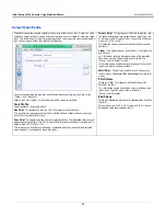
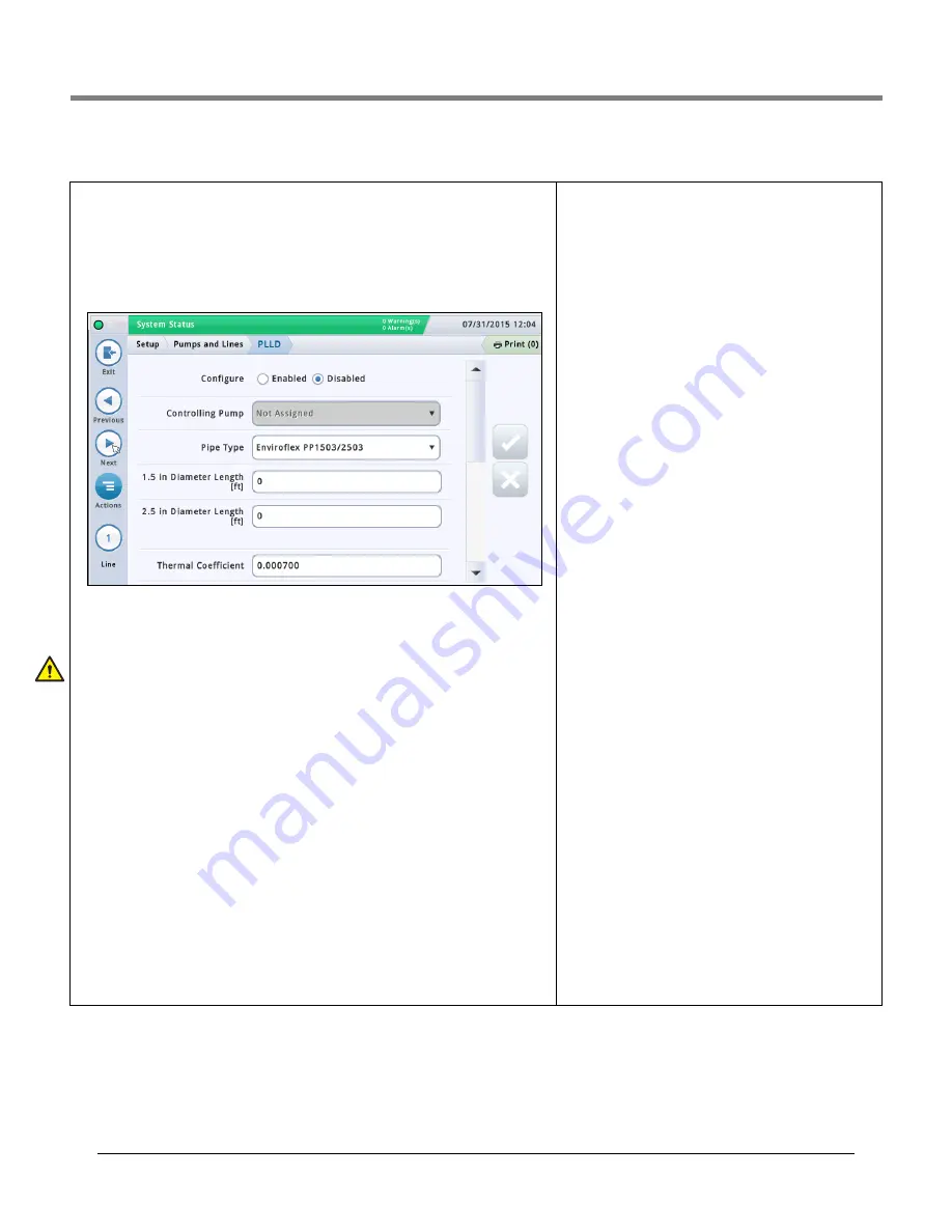
This screen lets you setup para

m

eters for individual lines when Pressurized Line Leak Detec-

tion (PLLD) is enabled. Also, if 

Leak Monitoring

 is not enabled (in “Setup>Pu

m

ps and 

Lines>Line”) for at least one line, then none of the PLLD screens can be edited.
The 

m

axi

m

u

m

 nu

m

ber of lines that can be configured for Leak Detection is equal to the 

m

ax-

i

m

u

m

 nu

m

ber of STPs as deter

m

ined by your console. However, only those lines for which 

Leak Monitoring is enabled (in “Setup>Pu

m

ps and Lines>Line”) are shown.

Auto

m

atic dialing or sending of PLLD alar

m

s is setup in Auto

m

atic Events setup (Setup> 

Auto

m

atic Events). 

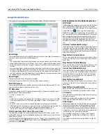
Select a line fro

m

 the icon list on the botto

m

 of the screen to configure.

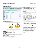
Configured

Touch the radio button to enable or disable the PLLD feature for the selected line.

NOTE: In setup wizard, you should enable settings as you go.

Controlling Pump

Touch to enter pu

m

p controlling this tank. Note: Pu

m

m

ust be progra

mm

ed to use Pu

m

Control (see “Setup>Pu

m

ps and Lines>PLLD” on page 42).

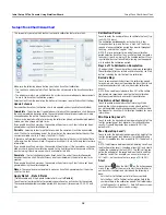
Pipe Type

Touch to enter the pipe type for this line. 

Refer to the ‘Supported Pipe Types and Line Lengths’ 

table in the Veeder-Root Electronic Line Leak Detectors Application Guide (P/N 577013-465).

NOTE: The fields that display below are dependent on, and applicable to, the Pipe Type 
selected. For exa

m

ple, if you select 2/3 IN. FIBERGLASS, the applicable fields that display 

will allow you to enter lengths for the 2" dia

m

eter and the 3" dia

m

eter pipe. If you select 

"user defined" pipe type, fields for setting up the 1st and 2nd line dia

m

eters, line lengths, 

and bulk 

m

odulus will display.

Line Length

The length of the piping between the tank and the dispensers, including the length between 
the check valve and where it connects into the product line. Line lengths are whole nu

m

bers. 

Values are in foot or 

m

eter incre

m

ents, depending on syste

m

 units.

Allowable selections: 

Refer to the ‘Supported Pipe Types and Line Lengths’ table in the 

Veeder-Root Electronic Line Leak Detectors Application Guide (P/N 577013-465).

The default is 0 but leaving it at 0 after entering a line length will cause a data setup warn-
ing.

Line Diameter

Allowable selections: 0 to 3.00 in (0 to 76.20

mm

)

The default is 0 but leaving it at 0 after entering a line length 
will cause a data setup warning.

2nd Line Length

Allowable selections: 

Refer to the ‘Supported Pipe Types and 

Line Lengths’ table in the Veeder-Root Electronic Line Leak 

Detectors Application Guide (P/N 577013-465).


Default: 0

2nd Line Diameter

Allowable selections: 0 to 3.00 in (0 to 76.20

mm

)

The default is 0 but leaving it at 0 after entering a line length 
will cause a data setup warning.

1st Line Bulk Modulus

[only available if the pipe type is user-defined]
The line's resistance to unifor

m

 co

m

pression.

Refer to the ‘Supported Pipe Types and Line Lengths’ table in 

the Veeder-Root Electronic Line Leak Detectors Application 

Guide (P/N 577013-465).

Allowable selections: 1000 to 200,000 psi (6892 to 
1,378,359kPa).
The default is 0 but leaving it at 0 after entering a line length 
will cause a data setup warning.

2nd Line Bulk Modulus

[only available if the pipe type is user-defined]
The line's resistance to unifor

m

 co

m

pression.

Refer to the ‘Supported Pipe Types and Line Lengths’ table in 

the Veeder-Root Electronic Line Leak Detectors Application 

Guide (P/N 577013-465).

Allowable selections: 1000 to 200,000 psi (6892 to 
1,378,359kPa)
The default is 0 but leaving it at 0 after entering a line length 
will cause a data setup warning.

Thermal Coefficient

If the controlling pu

m

p assigned to the line has a tank 

assign

m

ent, this field is set to the ther

m

al coefficient fro

m


that tank (see “Setup>Tank>General”) and the field is 
read-only. If there is no tank assign

m

ent, you can edit this 

field. If the tank assign

m

ent is re

m

oved, the syste

m

 will use 

the default ther

m

al coefficient 0.00070 U.S. Units (0.00126 

Metric Units).
Allowable selections: 0.0 to 0.0016 gal./gal./°F (0.0 to 
0.00288 lit./lit./°C) 

Summary of Contents for TLS-450PLUS

Page 1: ...TLS 450PLUS TLS4 Manual No 577014 110 Revision B Operator s Manual...

Page 2: ...l or consequential damages in connection with the furnishing performance or use of this publication The information contained in this publication may be subject to change without notice This publicati...

Page 3: ...sole Using Workflow Wizard Initial Screen Menu Setup Workflow Wizard Setup Workflow 9 Setup Display Language Units 9 Setup Date and Time 9 Setup Display Date Time Format 10 Setup Display Number Format...

Page 4: ...kup Menu Software Maintenance DB Backup 60 Example Database Backup Procedure 60 DB Restore Menu Software Maintenance DB Restore 61 Download Menu Software Maintenance Download 62 Example Software Downl...

Page 5: ...ing valid Installer Certification are approved to perform wiring and conduit routing equipment mounting probe sensor and carbon canister vapor polisher installation wireless equipment installation tan...

Page 6: ...0 See Example Status Bar Status Bar Types Below Date Time Print Button Normal Warning Alarm SYSTEM STATUS 0 Warning s 0 Alarms s SAVING 0 Warning s 0 Alarms s T2 DELIVERY NEEDED 1 Warning s 0 Alarms...

Page 7: ...e See Workflow Wizard setup Actions Icon Touch to access Help Touch the Help icon to open On Board Help Also if the Shifts feature is set up touching the Actions icon will display the Close Shift icon...

Page 8: ...e field would be white and touching the down arrow would display the additional printers Touching in a white field displays a pop up keyboard keypad to enter or modify an entry Selected device Touch t...

Page 9: ...t Both ports of ethernet 2 are programmed the same Ethernet port 1 upper Ethernet port 2 middle and lower switched Front of Console Port 2 Bottom of console Port 1 Selectable Comm Device slots Fixed C...

Page 10: ...your finger up to scroll down or move your finger down to scroll up Repeatedly touch the side TOC scroll bar upper arrow to scroll up or repeatedly touch the side scroll bar down arrow to scroll down...

Page 11: ...ctions to begin the download Once the download process has completed you must activate the software see Activate Revert Screen Menu Software Maintenance Activate Revert on page 58 System Status 07 20...

Page 12: ...ted to the power panel and to all site monitored devices apply power to the console and let it boot up and display the Home Screen see below Figure 3 Initial Setup Home Screen Access Workflow Wizard S...

Page 13: ...dification the user would likely use the standard quicker path from the home screen to the desired screen e g Menu Setup etc etc Setup Display Language Units Setup Date and Time System Language Touch...

Page 14: ...ll screens and reports Date Format Touch to enter desired date format Date Separator Touch to enter desired date separator Time Format Touch to select 24 hr time hh mm or 12 hour AM PM time hh mm AP T...

Page 15: ...that often go in and out of an alarm state in a short period of time In addi tion some alarm reports during the clear time are consolidated reducing their number without eliminating the alarm reports...

Page 16: ...name Touch to select the host name of the console as it appears on the customer s network in this example TLS 450PLUS The default host name can be changed to accommodate the cus tomer s network needs...

Page 17: ...rol C char acter ASCII 03 ETX Characters Computer Field enabled only if RSR 232 End of Message field is enabled End Of Text ETX character ETX is programmable if enabled via the S53100f command If it i...

Page 18: ...the ETX Characters Display and ETX Characters computer fields below ETX Characters Display Field enabled only if RSR 232 End of Message field is enabled End Of Text ETX character ETX is programmable...

Page 19: ...Interface Module port This is used at sites where the console communicates to the dispensers via Ethernet TCP IP instead of the typical serial communications pathway Select a TDIM port from the icon...

Page 20: ...SF tank gauge present on a network must have a unique node ID The default is 01 but you can change it as required This field is not available with the LON Module device option NOTE With a LonWorks car...

Page 21: ...er to the customer s third party device for the type of code to enter in the ETX Characters Display and ETX Char acters computer fields below ETX Characters Display Field enabled only if RSR 232 End o...

Page 22: ...s SMTP Server Password Relayhost Smart host Password Touch to enter the server password or shared secret for the server maximum 25 characters SMTP Server Requires SSL Relay Requires SSL When enabled i...

Page 23: ...talled and X is the connector input to which the device is attached from 7 to 12 LVDIM inputs connected to the console will display the fol lowing possible address codes in the Address Field B1 Sx X w...

Page 24: ...m Mag FLEX probes with Low Level Water Float only Touch to enter the Water Minimum value listed in the 577014 056 manual Invalid Fuel Touch to enter the Invalid Fuel value listed in the appropri ate k...

Page 25: ...nning continuously for a period exceeding the Max Run set in Setup Pumps and Lines PLLD TLS 450PLUS only Orientation Touch to select External Input orientation Normally Open Normally Closed LIQUID SEN...

Page 26: ...Water Alarm Touch to enter the height at which this Mag sensor will activate the water alarm MAG SENSOR SETUP Concluded Water Warning Touch to enter the height at which this Mag sensor will activate...

Page 27: ...phanu meric characters that will appear on the console screens and in reports Serial Number Read Only Console auto detected serial number of this ATM pressure sen sor VAPOR PRESSURE SENSOR SETUP Set u...

Page 28: ...y receipts in the BIR variance amount calculation Select this if the ticketed delivery feature is enabled in the Setup Delivery screen Temperature Compensation Touch to enter the method for calculatin...

Page 29: ...tored Rolling Days period For example you select Rolling Consecutive test type and enter 10 in Rolling Days field The test starts March 1 On March 10 a report is generated for days March 1 March 10 On...

Page 30: ...k at 100 height this volume is provided by the tank manufacturer Diameter Touch to enter the inside diameter of the tank look for this dimension on the tank chart provided by the manufacturer Tank Til...

Page 31: ...ick height is not used for volume calculation it is for display only Delivery Delay Because the system has the ability to detect a delivery automatically the time entered in this field represents the...

Page 32: ...alarms occur when the volume of product in the tank drops to a level at which you should request a deliv ery This is referred to as the minimum operating capacity Set this value at a volume higher th...

Page 33: ...s from being triggered do not set the limit value to identify losses of 0 2 gph 0 76 lph or less during the test period The leak alarm limit should be set to identify losses of 1 gph 4 lph or greater...

Page 34: ...e posting a test result The minimum wait time after delivery when a test can be run is 5 hours and the minimum test duration is 1 hour Test Frequency Touch to select the frequency for SLD tests as des...

Page 35: ...ak test on siphon manifolded tanks the fol lowing is required A siphon break solenoid valve is installed between the two siphon mani folded tanks Both the Tank Test Notify field above and the Tank Tes...

Page 36: ...hich is 75 of 96 or 72 This selection can be used for all rounded and dished end tanks and should be selected when AccuChart is available for these type tanks Twenty Point This option uses 20 Points t...

Page 37: ...t status of the chart Active Ready Incomplete Bad Point Calculating Making a Chart Active for a Tank Select a tank from the icon list on the bottom of the screen to view that tanks available chart s S...

Page 38: ...mit An hourly limit in the variance in inventory that when exceeded generates an alarm The default warning limit is 4 litres Min value is 1 litre and max value is 400 litres Maximum Volume Limit An ho...

Page 39: ...hon set number from the siphon set list that displays along the bottom of the screen 2 In the Available Tanks column select the first tank you want as part of this new siphon set and press This moves...

Page 40: ...tion is set to Enabled Entering Values for the CSLD Evaporation RVP Chart Once enabled see above and you select inside the RVP field box a popup window appears that lets you view or enter RVP entries...

Page 41: ...lets you map a specific tank to a product Depending on your site you could have two or more tanks with the same product By properly mapping your tanks to the products you can group single and manifold...

Page 42: ...ded periodic selection period is 14 days apart for example 14 28 42 and 56 Calibration Period Touch to enter the number of days to calibrate the tank typ ically 30 120 days The calibration period depe...

Page 43: ...eriod for Immediate and Complete update selections the cali bration will be attempted at the next date change The update will be done with this calibration or the last generated calibration or AccuCha...

Page 44: ...ted is already assigned to another pump this alert is not an alarm or error since some sites use a single pump control output for more than one pump NOTE There may be both configured and non configure...

Page 45: ...settings below Manifolded Sequential1 2 If there is more than one tank with a pump on the line tanks are pumped one at a time until the volume drops below the Pump Threshold value set in the Setup Tan...

Page 46: ...ents depending on system units Allowable selections Refer to the Supported Pipe Types and Line Lengths table in the Veeder Root Electronic Line Leak Detectors Application Guide P N 577013 465 The defa...

Page 47: ...runs only when manually started in Diagnos tics PLLD Manual Tests Passive 0 1 gph 0 38lph Line Leak Test only available if the pipe type is user defined and the 0 1 gph 0 38lph Line Leak Test is set t...

Page 48: ...the site is unattended You should lock out the lines during these hours Line Lockout Schedule Touch to select a schedule for lockout events Disabled No lockout events scheduled Daily Allows for one l...

Page 49: ...ired time This lets you stop dispensing from the line until an Annual test is completed Days before Annual Warning The number of days before the Annual Test Needed Warning is triggered Allowable selec...

Page 50: ...but the tank s must be idle before a shift can close Once a timed shift has been closed no other shift can be closed until the shift duration ends Manual You close a shift directly on the console by...

Page 51: ...very Ticketed Delivery If you enable ticketed delivery you can manually enter tick eted volumes using the receipts from delivery trucks Enabling this feature generates reports showing delivery varianc...

Page 52: ...p screen must be changed on the console directly Modem Number of Retries Number of times the console attempts to connect if the last connection attempt fails Modem Retry Delay Time Amount of time to w...

Page 53: ...below Touch to enter an amount of time up to 240 minutes to wait before the console retransmits the message up until the alarm is cleared AutoXmit Alarm List Leak Alarm High Water Alarm Overfill Alar...

Page 54: ...elect Actions Add Task 2 Touch the fields below to enter the appropriate information Connection Mode Modem To use a USB modem must be installed to the console Remote TCP IP Address To use an Ethernet...

Page 55: ...ting A Task 1 Do the following If editing a task select a task record to modify a checkmark appears next to the entry then select Actions Edit Task If adding a task select Actions Add Task 2 Touch the...

Page 56: ...inter Printer device label Adding or Editing A Task 1 Do the following If editing a task select a task record to modify a checkmark appears next to the entry then select Actions Edit Task If adding a...

Page 57: ...ct tasks Screen Column Descriptions Ev Id Identifier automatically assigned to an event by the console Time Event Time or event that triggers the device related task e g Leak Alarm Disabled may have m...

Page 58: ...he screen to exit the screen Adding a Role available to an Administrator user only 1 Touch Actions Add Role 2 Enter information in the Add New Role fields as described below 3 Touch to save your entry...

Page 59: ...ble In that situation reassign users to another role or delete users assigned to that role before deleting that role 1 Select a role to delete a checkmark appears next to the entry then select Actions...

Page 60: ...to that user and or an Adminis trator user NOTE there has to be at least one user with an Admin role You may need to edit a user if a person s responsibility has changed and you need to reassign thei...

Page 61: ...System Administration Users Admin screen Once the Front Panel Security field is enabled you must enter the correct password or you will remain in the logged out mode In the logged out mode you can on...

Page 62: ...en Menu Software Maintenance Activate Revert This screen lets you activate newly installed software or revert to a previously stored version of software During the activation process several dialog bo...

Page 63: ...sion of soft ware has not been stored Current Operation Status of the console Idle no software is being installed or reverted or Activating a software install is in progress Connection Message Not app...

Page 64: ...backup the Backup Completed Successfully message appears Table 2 DB Backup Screen Field Descriptions Field Description Current Version Current version of software x xx xxx x installed in the console A...

Page 65: ...ecuting or Discovering Restore Device system is validating installed thumb drive Restore Operation in Progress restore is in progress Connection Message Lists any messages that may occur between the d...

Page 66: ...ole Idle no backup procedure is executing Scanning Devices system is validating installed thumb drive Reading Update List Downloading Connection Message Lists any messages that may occur between the d...

Page 67: ...Software Maintenance System Snapshot If a problem cannot be diagnosed over the phone with technical support Tech Support may request a System Snapshot be taken and returned V R The System Snapshot cap...

Page 68: ...you of key events During feature activation which only takes a few minutes there must be no dispensing Following activation the console converts the setup databases Once new features are installed se...

Page 69: ...For technical support sales or other assistance please visit www veeder com...

Reviews: