
Mag Probe Installation
Entering Custom Float Size (In-Tank Setup - Ver. 22 or later)
36
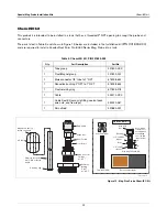
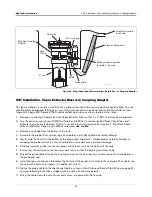
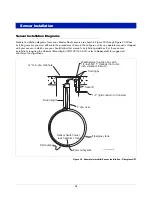
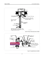
INSTALLING THE PROBE IN THE STAINLESS STEEL TUBE
1.
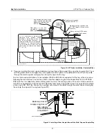
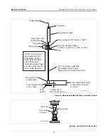
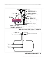
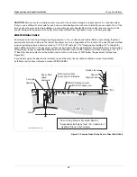
Slide the rubber rain shield onto the probe shaft (narrow end up) and push it all the way up to the probe
canister. Gently slide the probe down into the tube until it rests on the bottom of the tube. Slide the rain shield
down the shaft until it rests against the top end of the tube. The lower (wide) end of the shield may be a little
over the top of the gland nut. Note: the rain shield is intended to keep water out from between the probe’s
shaft and the inside of the tube so you don’t want to force the shield down below the top end of the tube (see
Figure 29).
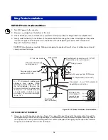
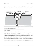
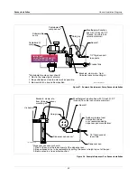
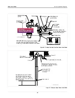
2. Attach the warning tag as shown in Figure 28. Attach the probe cable connector to the mating plug on the top
of the probe canister. Hand tighten the connector securely.
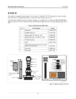
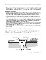
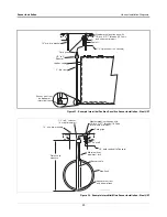
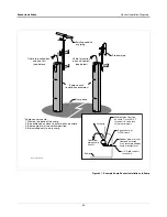
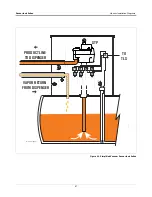
3. If required by local regulations, install a protective housing. A typical housing consists of a reducer, 4-inch
diameter pipe, and union. The final assembly must comply with local codes.
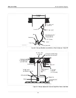
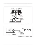
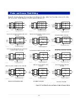
4. Splice and seal the wires as shown in the Probe and Sensor Field Wiring on page 51.
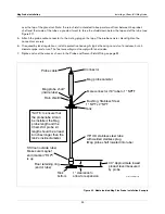
Entering Custom Float Size (In-Tank Setup - Ver. 22 or later)
At the console, select Setup Mode/In-Tank Setup/Float Size. Press Change to display “Float Size: Custom”
1
. For
the LPG probe you need to enter a Fuel Offset value of +0001.120 and an Invalid Fuel value of +0003.250.
(Water Offset and Water Minimum values are ignored for this probe so no changes are necessary). The probe is
now installed and setup.
1. This offset can be entered using a “Tilt” value of +1.06” and 2-inch float entry on earlier software versions.


