Mag Probe Installation
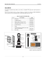
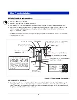
Installing a Chem-ISO Mag Probe
32
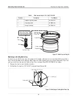
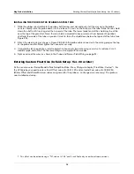
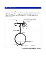
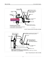
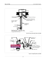
ATTACHING THE FLOAT TO THE TUBE
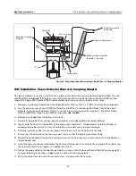
Slide the large shipping washer off of the stainless steel tube and discard it. Carefully slide the stainless steel float,
non-magnet end first, onto the tube and down against the retaining ring at the bottom of the tube (the float end
marked “TOP” should be facing up). The float must be installed magnet-end up to measure fuel correctly (see
Figure 26).
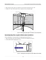
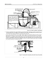
INSTALLING THE STAINLESS STEEL TUBE INTO THE TANK
1.
With the float against the retaining ring, carefully lift the open end of the tube up and lower the assembly, float
end first, into the tank until the tube rests on the bottom of the tank (Figure 26). Carefully slide the 1” x 2”
stainless steel bushing, 2” end first, down over the tube until it rests against the tank opening. Apply UL
classified sealant suitable for use with the product in the tank to the outside bushing threads that will be
screwed into the tank fitting. Screw the bushing into the tank fitting. Tighten the bushing as required to ensure
a proper seal.
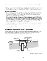
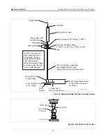
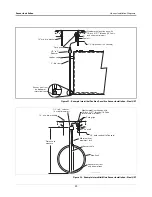
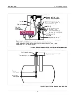
SEALING THE STAINLESS STEEL TUBE IN THE TANK OPENING
2. Loosen the gland nut on the male connector. Carefully slide the male connector, 1” end first, down onto the
tube until it rests against the bushing. Apply UL classified sealant suitable for use with the product in the tank
to the threads of the connector’s NPT threads. Screw the connector into the bushing. Tighten the connector
as required to ensure a proper seal.
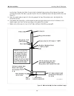
3. Push the tube down until it rests on the tank’s bottom. Using a felt marker, make a mark on the tube at the top
of the gland nut. Raise the tube until the mark is 1-inch above the nut, then hand tighten the gland nut until the
tube is held in place (this distance is necessary for expansion and contraction of the tank). Tighten the gland
nut one and one quarter full turns beyond hand tight to crimp the ferrules to the tube and create the proper
seal.
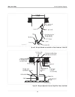
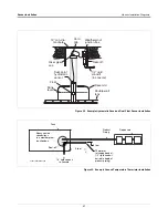
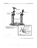
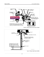
INSTALLING THE PROBE IN THE STAINLESS STEEL TUBE
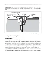
4. Slide the rubber rain shield onto the probe shaft (narrow end up) and push it all the way up to the probe
canister. Gently slide the probe down into the tube until it rests on the bottom of the tube. Slide the rain shield
down the shaft until it rests against the top end of the tube. The lower (wide) end of the shield may be a little
WARNING
Fire or explosion resulting in serious injury or death could result if the equipment is
improperly installed or modified.
1. It is essential that you carefully read and follow the warnings and instructions
in this manual to protect yourself and others from serious injury due to fire or
explosion. Failure to do so could result in undetected potential environmental
and health hazards.
2. Comply with all federal, state, and local codes, and other applicable safety
codes. All wiring must comply with UL/cUL standards and other local
electrical and pressure vessel codes.
3. Failure to comply with these requirements could result in death, serious
personal injury, property loss, or equipment damage.
4. Substitution of components may impair intrinsic safety.
5. Circuitry within the probe and console barrier form an intrinsically safe,
energy limited system. The probe wiring is intrinsically safe only when
connected to Veeder-Root consoles having form numbers 8470, 8482, 8485, or
8560.


