11
DIS-51 To TLS Console Wiring Connections
Connection Instructions - DIS-51 to TLS4
Connection Instructions - DIS-51 to TLS4
RS-485 Serial Port Configuration On TLS4
1.
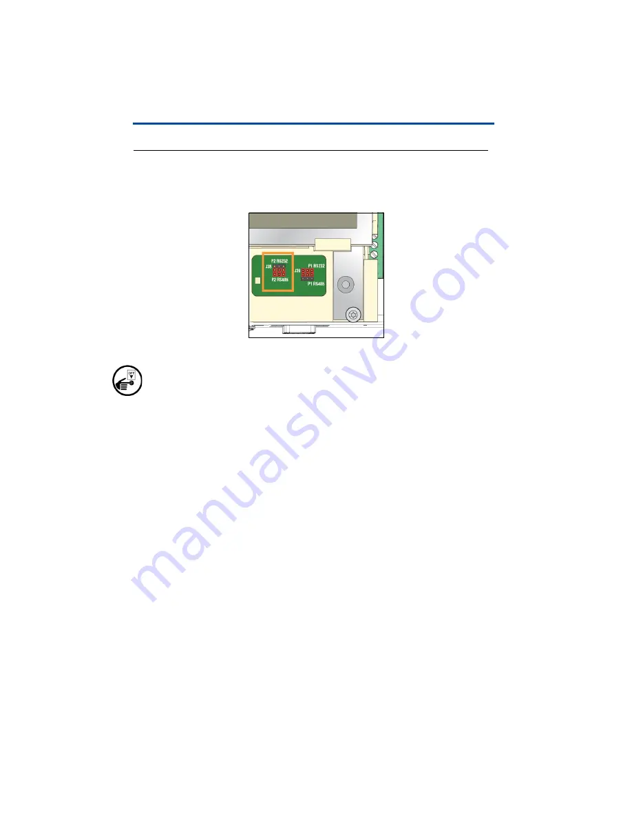
Put all three jumpers for the Serial Port 2 (J38) into position P2-RS-485 as
shown in Figure 6.
Figure 6. Serial Port 2 J38 Jumpers Set To RS-485 Positions
a. Turn off power to the TLS4 Console.
b. To reach the jumpers, remove the housing lid. The jumpers are located near
the lower right side of the display.
c. Close to the jumpers there are the two LEDs D15 (Rx, green) and D16 (Tx,
red) that indicate the status of the Rx and Tx lines of port 2.
d. When the communication between the DIS-51 Display and the TLS-4 is
established, both LEDs should light up periodically.
Wiring Diagram
Figure 3 shows the wiring connections between the DIS-51 junction box and the
TLS4 Serial 2 Port.
Software Setup For TLS4 Serial 2 Port
Go to Menu>Setup > Communication > Serial Port and select
Serial Port 2
.
Enter the following parameters:
• Label - e.g. DIS-51 Display
• Usage - RS-485
• Baud Rate - 9600
• Data Bit - 8
• Parity - No Parity
Summary of Contents for DIS-51
Page 1: ...Manual No 577014 445 Revision C DIS 51 Installation Setup Operation Guide ...
Page 10: ...6 Introduction Wiring Connections Figure 2 DIS 51 Junction Box Wiring Diagram ...
Page 11: ...7 Introduction Wiring Connections Figure 3 Serial Comm Wiring Input Options ...
Page 31: ...27 Operating Instructions Alarm screens This page intentionally left blank ...
Page 32: ......


