


3
Wanner Engineering, Inc.
United States
Instant Information: www.vectorpump.com
(61) 33-5681 Fax (61) 33-6937 VEC-991-400A
Vector Series Installation
Pump Test and Installation
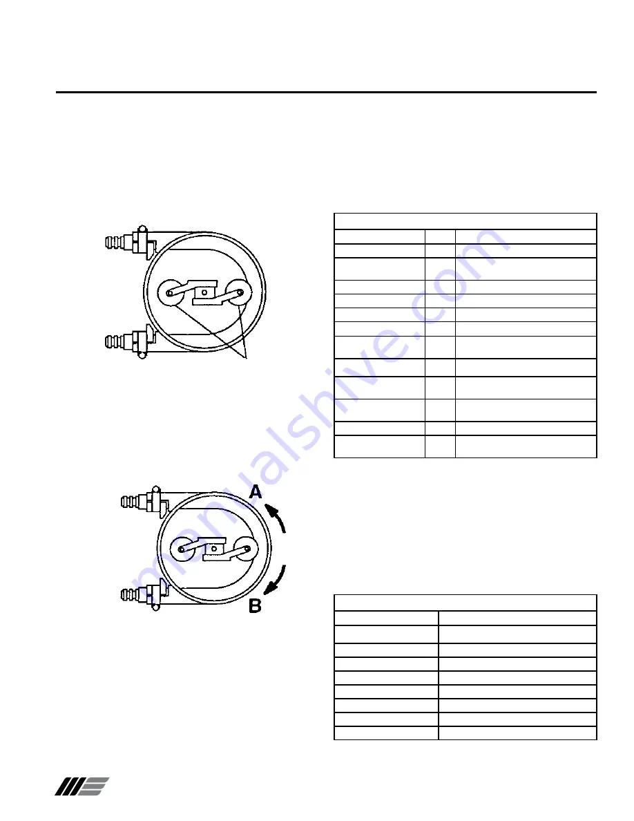
Before you install the pump in the system, set the direction of
pump rotation and the position of the pressure rollers:
1. Remove front cover from pump (four screws).
2. See Figure 1. For easier adjustment, check that pressure
rollers are in position shown (one roller compressing middle
of hose, and one roller free).
Note:
Model 2006 and 2007 pumps use a different rotor
assembly than the one shown.
Before Initial Start-Up
Before you pump fluid through the system, be sure that:
1. All shutoff valves are open.
2. All connections are tightly secured.
3. See Hose Identification Table. Hose material is compatible
with fluid being pumped, and hose design matches duty cycle
and discharge pressures.
Material Operating Temperatures
Material
Operating Temperatures
EPDM
0 to 180˚ F
Hypalon
0 to 180˚ F
Neoprene
50 to 130˚ F
Silicone
0 to 180˚ F
Varprene
0 to 160˚ F
Natural Rubber
0 to 185˚ F
Nitrile Rubber
0 to 160˚ F
Pharmed
®
0 to 180˚ F
Hose Identification
Extruded
Code
Description
Hypalon
HE
Black color, shinny smooth surface
Neoprene
PE
Flat black color, rough surface, rubber
smell
Varprene
VE
Cream color, smooth surface
Silicone
SE
Rust color, smooth surface
Pharmed
®
FE
Cream color, Pharmed
®
name on hose
Fiber Braided
Hypalon
HF
Black color, yellow stripe, double
braided
EPDM
EF
Black color, white stripe, double braided
Natural Rubber
NF
Black color, green stripe, double
braided (standard duty)
Natural Rubber
MF
Black color, no stripes, thick double
braids (heavy duty)
Nitrile Rubber
BF
Black color, white inner hose
Nitrile Rubber - Oil Rated
OF
Black color, HBRF-HY-K stamped on
hose
W0455
W0456
Pressure
Rollers
Figure 1
W0456
DISCHARGE
INLET
Figure 2
3. Connect incoming power supply to motor (refer to motor
manufacturer’s instructions).
4. See Figure 2. Run pump and check direction of rotation,
“A” or “B” as shown. All pumps must rotate in direction “A“
(counterclockwise). To reverse rotation, exchange two of
three wires that connect incoming power to motor.
5. Set pressure rollers (see “Service: Setting the Roller
Pressure”). Roller pressure is not set at factory, because it
must be adjusted to compensate for size of inlet and discharge
lines and specific gravity of fluid being pumped.
6. Verify all fasteners are properly tightened.
7. Reattach front cover.
8. Install pump in system.
4. See Material Operating Temperatures Table. Temperature of
fluid pumped is within operating temperature range of hose
material installed in pump. Hose material can be identified by
5
th
and 6
th
digit of pump model number. E.g. 2007-NF-BB-D2,
where ‘NF’ designates natural rubber.
CAUTION
: Contact factory when pumping a fluid that is
within 15˚ F of the maximum hose temperature. Take safety
precautions to insure hot pumpage does not harm operators
if a hose leaks.


