


4
Basic configuration
(e. g., SAE J1939)
CAN bus 1
CAN bus 1
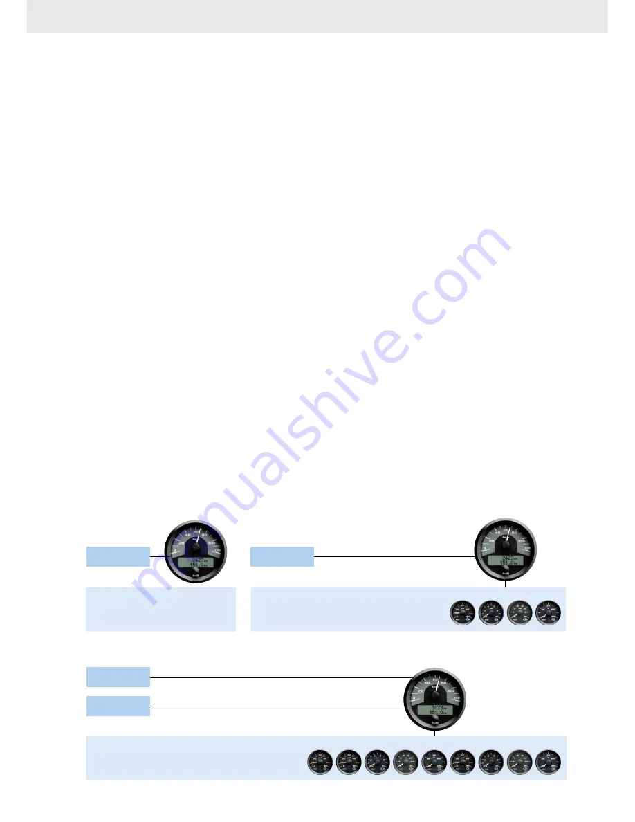
Standard configuration
Complex configuration
Analogue
CAN bus 1
Variable configuration
options
CANcockpit, the flexible solution for a wide range of
applications, offers numerous configuration and ex-
pansion options. It is based around a central instrument
which can be either a tachometer or a speedometer.
The central instrument features two CAN inputs sup-
porting different CAN protocols, two frequency in-
puts, three resistive inputs, one 4–20 mA input, plus
one 0–5 volt input. In addition, it is equipped with two
switched outputs, a configurable digital display field
and more. Three sample standard applications are
shown below:
Basic configuration
Sample requirement:
A generator is to be fitted with a tachometer measur-
ing up to 3,000 rpm. There is only one CAN bus;
the limit values and settings are clearly defined.
CANcockpit provides the solution:
Once the tachometer has been set up as the central
instrument you will have access to the desired tacho-
meter display and the op tion of viewing other data,
e. g., as part of an inspection routine, as and when
required. All data can be displayed on the central
instru ment, allowing you to monitor current engine
data at any time without the need for other satellite
instruments.
Standard configuration
Sample requirement:
Instrumentation for a digger is one example of a
standard configuration using CANcockpit. A tacho-
meter and four more instruments need to be added
to a CAN bus.
CANcockpit provides the solution:
Once the instrumentation solution has been program-
med (a simple procedure), key engine data such as
coolant/engine oil/ transmission oil temperatures will be
displayed alongside rpm and operating hours, plus
fuel level – giving you a clear overview of crucial infor-
mation at all times.