8
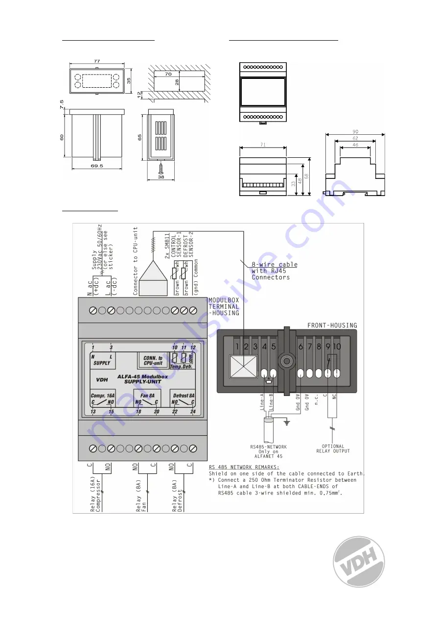
* Dimensions CPU-unit.
* Dimensions SUPPLY-unit.
* Connections.
Page 1: ...it is shown how sensors and power supply are to be connected After connecting the ALFA NET 45 to the power supply a self test is started As this test has finished the measured temperature of the produ...
Page 2: ...t cycle the defrost can by manually stopped by pushing the UP key and than the SET key while the UP key is hold Start defrost If there is no defrost cycle the defrost can be started manually by pushin...
Page 3: ...er P26 1 Startup delay after power failure Offset defrost sensor Fan off delay if parameter P22 1 Readout defrost sensor 1 15 C 50 50 C 50 50 C 15 15 C 0 3 0 99 1 99 Hours 0 99 Minutes 99 99 C 99 99 C...
Page 4: ...e of the following parameters is set to 1 the fan can be stopped Parameter 19 1 Fan switch differential active The fan is only active when the defrost temperature is parameter 13 C lower then the meas...
Page 5: ...st is started when the compressor has run for parameter 7 hours after the last defrost Parameter 25 1 The temperature readout on the display is locked during defrost cycle Parameter 26 1 After power u...
Page 6: ...play of the ALFA NET 45 the following error messages can appear E1 Product sensor error Fatal error display shows E1 and all relays are deactivated accept when parameter 24 is 1 then the compressor an...
Page 7: ...se see Product sticker Max used power 6 2 VA Fuse No internal fuse present Product sensor SM 811 2m Defrost sensor SM 811 2m Relay Compressor SPST 250V 16A C NO cos phi 1 Relay Defrost SPST 250V 8A C...
Page 8: ...8 Dimensions CPU unit Dimensions SUPPLY unit Connections...