background image


-

8 - 


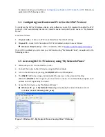
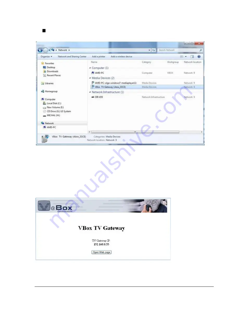
Windows 7 – go to

 Network > Media Devices

, right click 

VBox TV 

Gateway (vbox_xxxx) 

and select 

View device webpage

 from the context menu. 


Figure 2: Windows 7 

– Network Media Devices showing VBox TV Gateway


NOTE

: The XTV Ex device’s default name is 

VBox XLVe TV Gateway (vbox_xxxx

), where “xxxx” is the 

product’s number. This name appears on devices that are connected to your network and have the 
UPnP Protocol enabled. as explained in the next section, you have the option to rename this device 
(using  the 

System  Name

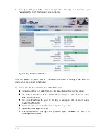
  property).The  XLV  Ex  TV  Gateway  Web  interface  is  displayed,  showing  its 

Welcome page 


Figure 3: VBox XLVe TV Gateway interface 

– Welcome page 


Summary of Contents for XLV Ex Series

Page 1: ...Quick Guide Installation Tuning and Streaming Document Revision 3 0 XLV Express DVB TV Gateway ...

Page 2: ... 3 11 SHUTTING DOWN AND RESTARTING THE SYSTEM 18 3 12 SYSTEM RESTART 19 4 CONFIGURING TUNER 20 4 1 CONFIGURING THE SATELLITE TUNER DVB S S2 20 4 2 CONFIGURING TUNER PARAMETERS FOR DVB S2 RECEPTION 23 4 3 CONFIGURING XLV EX 4143 UNICABLE MODELS 26 4 4 DISEQC CONFIGURATION 28 4 4 1 Edit an existing DiSEqC command 30 4 5 CONFIGURING THE TERRESTRIAL TUNER DVB T 31 4 5 1 Tuning by Physical RF Channel N...

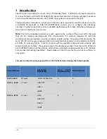
Page 3: ...ously from transponders the optional reception of restricted conditional access broadcasts and the possibility of data casting Throughout this document the term XLV EX will be used in general when discussing features common to all members of the XLV EX DVB TV Gateway family Specific products will be explicitly mentioned when dealing with features particular to them The captions used in this docume...

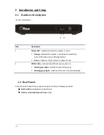
Page 4: ...144 XLV Ex 4174 Rear Pane Item Description 1 Power LED indicates whether the system is ready Orange indicates the system is connected to electricity but is still in the process of being started Green indicates the XLV device is ready for use 2 STATE LEDs indicate the traffic status in tuners 1 4 Steady green light indicates a locked frequency Blinking green light indicates this tuner is transmitti...

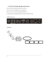
Page 5: ...ive RF connectors The 4 Tuner can be set independently or as Unicable SCR Each one for can be connected to independent satellite feed Or operating mode of Unicable SCR when one RF connector feed for all tuners XLV Ex 4134 Rear Panel XLV Ex 4134 Unicable Multiswitch Unicable Multiswitch ...

Page 6: ...F connectors that feeds 4 tuners XLV Ex 4144 74 Sanrio Rear Panel XLV Ex 4144 74 operating when one RF connector feed for all tuners XLV Ex RF ConnectorXTi Unicable RF1 מותאם האם ל XLV Connector Tuner Tuner 1 DVB S2 Tuner Tuner 2 DVB S2 Tuner Tuner 3 DVB S2 Tuner Tuner 4 DVB S2 ...

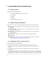
Page 7: ...e device Keyboard monitor and monitor cable or Laptop PC station Ethernet cable Unicable device make sure you have a unicable device connected to your satelite see http en wikipedia org wiki Single_cable_distribution 3 3 Installing the XLV Ex TV Gateway Device To install your device take the following steps 1 Connect the Ethernet cable to the network and to the unit s designated connector 2 Connec...

Page 8: ... or disable network discovery Once UPnP is enabled you can access your XLV device using My Network Places as explained in the following section 3 5 Accessing XLV Ex TV Gateway using My Network Places 1 Make sure your PC is connected to a router 2 Connect the router to the XLV device using an Ethernet cable 3 Turn on the XLV device by pressing the ON OFF button on its back panel 4 The ON OFF LED tu...

Page 9: ...ce s default name is VBox XLVe TV Gateway vbox_xxxx where xxxx is the product s number This name appears on devices that are connected to your network and have the UPnP Protocol enabled as explained in the next section you have the option to rename this device using the System Name property The XLV Ex TV Gateway Web interface is displayed showing its Welcome page Figure 3 VBox XLVe TV Gateway inte...

Page 10: ...s the XLV Ex unit and set via default IP address Connect an Ethernet cable from the XLV Ex unit direct to your PC station The default IP address of the XLV Ex Ethernet card is 172 16 1 1 and Subnet Mask 255 255 255 0 Use a like IP address for your PC station for example 172 16 1 2 and Subnet mask 255 255 255 0 Open a Web browser such as MS Internet Explorer on your PC Input the URL as http 172 16 ...

Page 11: ...ing the Ethernet configuration using the HTML Interface And Incorporating the XLV Ex into your Network To change the Ethernet interface configuration using the HTML interface 1 Select the SYSTEM NETWORK Update option The following screen displays ...

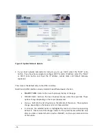
Page 12: ...ee different levels of action MAJOR TABS Refer to the row of optionsat the top of the page MINOR TABS Refers to the row of options directly under the major tabs These options change depending on the major tab selected Options Refers to the list of options on the left side of the screen These options change depending on the major and minor tabs selected In all cases the selected option is highlight...

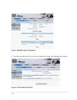
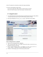
Page 13: ... 12 Figure 7 Modify Network Configuration 3 Click the CHANGE NETWORK SETTINGS button to validate the changes The following screen displays Figure 8 Activate Network Settings ...

Page 14: ... change the password used to access the HTML interface proceed as follows 2 Select the SYSTEM MANAGE Change Password option The following screen displays Figure 9 Change Password webadmin 3 Input the current password initially webadmin 4 Input the new password twice in the middle and lower form fields Verify that the new password contains 4 to 8 characters 5 Click the CHANGE PASSWORD button The me...

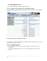
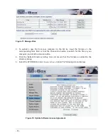
Page 15: ...een under SYSTEM MANAGE Figure 10 System Device and Software Information The information under the Software Versions heading indicates the software type and version installed as well as the type of unit in use 3 8 2 Loading New Software 1 Ensure the new software file extension ub is accessible on a disk on key or on your local computer 2 Select the SYSTEM MANAGE Manage Files option The following s...

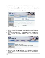
Page 16: ...ld or click the Choose File button to search for the file on your computer and click the UPLOAD button 4 Click the Refresh Directory Listing link and ensure that the filename is added to the directory listing 5 Select the SYSTEM MANAGE Update Software option The following screen displays Figure 12 Update Software License Agreement ...

Page 17: ...dio button and then click the PROCEED WITH UPDATE button The following screen displays Figure 13 Update Software File 7 Select the radio button for the appropriate software file under the Software Update Files heading 8 Click the UPDATE SOFTWARE button A message displays on screen informing that the update is in process Upon successful completion of the process the following screen displays Figure...

Page 18: ... 17 3 9 System Logger 1 Select the SYSTEM MANAGE System Logger option The following screen displays Figure 15 System Logger You can set here the Log Level Prints if necessary Debug operations ...

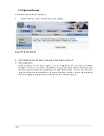
Page 19: ... Figure 16 System Restore Click Restore button All the configuration files will restore to the factory default 3 11 Shutting Down and Restarting the System To shut down or restart the system select the SYSTEM RESTART tab The following screen displays and system will reboot Figure 17 System Restart ...

Page 20: ...on Proper operation of the system requires it to be configured as per your DVB S and DVB T provider s instructions To achieve a DVB S T connection the device must be tuned to specific channels using the information supplied by your DVB S T provider You can tune the device using the physical Channel Number or its Center frequency number Follow the instructions below to configure the device s tuner ...

Page 21: ...t to achieve a satellite connection Note This chapter s settings apply to all tuners 1 4 Inputting Tuner Parameters HTML Interface To input the satellite parameters as informed by your satellite provider proceed as follows 1 Select the TUNER TUNER Update option The following screen displays Figure 19 Satellite Tuner Update ...

Page 22: ...e Low field or Dual and input both the low and high frequencies Frequencies must be entered in GHz Note Use the high frequency parameter only when a dual LNB is employed 4 Input the satellite frequency in GHz in the Frequency field under the Tuner Parameters heading 5 Input the symbol rate in KSym s 6 Select the polarization of the satellite feed either Vertical Right or Horizontal Left 7 If the L...

Page 23: ...gnal strength is within the acceptable range of 22 to 88 and yellow if it is outside of this range When the XLV EX is locked onto the satellite transponder at the current frequency the signal lock bar is green and states Lock Otherwise the bar displayed is yellow with the text Not Locked Select again Update option The following screen displays Figure 21 Satellite Tuner Update Locked 10 To unlock t...

Page 24: ...provide enhanced HDTV and MPEG 4 quality broadcasts The tuner requires a more specific configuration in order to stream DVB S2 broadcasts into your system To input this configuration please check with your satellite provider for the required information and follow the steps below 1 Select the TUNER TUNER Update option 2 Select DVBS2 option in the DVB Mode combo box The Update window displays again...

Page 25: ... Input the LNB parameters and initial tuner parameters as per instructions 2 6 in the previous section 4 Press UPDATE to apply the selected values The Status screen displays again showing all input parameters in the Current Tuner Settings section ...

Page 26: ... 25 Figure 24 DVBS2 Satellite Tuner Status Locked ...

Page 27: ...ting that is compatible with your XTV Ex Enable Unicable 4 Tuners Available compatible with Unicable models These models receive satellite broadcasting from a single coaxial cable and distribute this content through four tuners Disable Unicable Only 1 TunerAvailable compatible with all other XTV Ex models in which each satellite is connected to a single tuner 4 Input the Transmission frequency Ban...

Page 28: ...uency in GHz in the Frequency field under the Tuner Parameters heading 7 Input the symbol rate in KSym s 8 Select the polarization of the satellite feed either Vertical Right or Horizontal Left 9 After all of the parameters are input click the UPDATE button The Status screen displays ...

Page 29: ...tch MultiSwitch or Advanced 2 Input a unique name to identify this DiSEqC entry in the Name field e g Hotbird 13 0E 3 For Uncommitted switches uncheck the Committed Switch check box 4 Select the position from the Position drop down list 5 For MultiSwitch Select the LNB Option from the drop down list 6 Click the Add button The new entry will be added to list under the DiSeqC Command List ...

Page 30: ...Figure 28 DiSeqC command list 7 Select TUNER Tuner Update option Select added DiSeqC option from the Command drop down list The following screen displays Figure 29 Update Tuner Settings with DiSeqC command ...

Page 31: ... command you want to change The following screen displays Figure 30 Edit DiSeqC Command 2 Edit the desired fields Type Position LNB Option etc 3 Click on the Update button so save the changes 4 To delete the entry select the Delete This Entry check box and Click on the Update button to remove the entry ...

Page 32: ...an tune the device using the physical Channel Number or its Center frequency number Follow the instructions below to configure the device s tuner in the manner most convenient to you Note This chapter s settings apply to all tuners 1 4 For Change the product to the various of transmission e g DVB T T2 ISDBT ATSC see paragraph 4 6 4 5 1 Tuning by Physical RF Channel Number 1 Select the TUNER TUNER ...

Page 33: ...screen displays Figure 32 Display Tune by Channel Number 3 Select the desired RF channel number from the Channel Number drop down nu and press UPDATE The Status screen displays specifying the channel number in the Current Tuner Settings sections 4 and click Apply The following screen displays ...

Page 34: ...and that the signal strength is within the acceptable range of 22 to 88 If you do not achieve Locked status check the connection of the coaxial cable to the device and verify you entered the correct parameters If the problem persists contact your DVB T provider or your antenna installer ...

Page 35: ...34 Tuning by Frequency 2 Input the center frequency of the desired channel as supplied by your DVB T service provider in KHz 3 Select the information for the bandwidth parameter in the corresponding form fields as per your service provider s instructions 4 Click the UPDATE button The Status screen displays ...

Page 36: ... band s center frequency However in certain cases broadcasting channels are located at a frequency slightly different than the center frequency If you know the exact position of the channel in the band you can edit the RF channel number in the device so that it corresponds to the correct frequency position Follow the instructions below to edit the RF channel number 3 Click Edit Channels list butto...

Page 37: ...ct it at the Modulation drop down list otherwise select the Auto option 3 Click the corresponding UPDATE button The Edit Channel screen displays the input values 4 To restore frequency and modulation values to their original configuration click the RESET button under the Restore Default Table heading The Edit Channel screen displays the original values for each channel ...

Page 38: ...ogress 2 During the scan the Frequency is updated to show the scan progress 3 Once the scan is completed the page is updated to summarize the scan status and results Figure 38 Scan status and result 4 Select Select channel check box and click Tune to Selected Channel button Figure 31 status screen displays ...

Page 39: ...following transmission DVB T2 C ISDBT ATSC modes Select TUNER MANAGE Update option The followinnd screen displays Figure 39 configurations 1 Select one of the transmission configuration radio button and click Update button Following screen informed the system is getting rebooted displays 2 Upon reboot select TUNER Tuner Update option ...

Page 40: ...Follow the instructions in the next sub sections to configure the device for streaming as per your needs 5 1 Streaming to a Network After tuning the transponder and locking the signal you must select the individual channel you wish to stream to specific broadcasts destinations in your network 1 1 Select the STREAMING CHANNELS Update window A list of all stations broadcasting through the transponde...

Page 41: ...y pair one single IP address with different port numbers or different IP adresses with one single port number If you set the system to stream broadcasts only when at least one listener is present that is if the IGMP function is enabled different multicast IP addresses must be set in the configuration 5 In the Action column press the START button corresponding to the desired station The Update wind...

Page 42: ...media player for SAP reception Manage the the MANAGE options 5 2 Managing Multicast Distribution The XLV Ex device allows you decide whether streams are to be forwarded into the LAN only when at least one listener that is an entity actually connected to the stream is identified or at all times Making streaming conditional to the identification of listeners leads to a better use of the existing ban...

Page 43: ...as Enabled and offers the possibility of disabling IGMP Stream Programs Regardless of Listeners radio button 3 To disable the IGMP again select the Stream Programs Regardless of Listeners radio button and press SUBMIT The screen reverts to its original status as shown in Figure 22 5 3 Using Channel List Operations These options are the newest ones For details clarification how it works please appl...

Page 44: ...shows the current Enable On Demand Streaming status as Enabled and offers the possibility of disabling this feature Disable OnDemand Streaming radio button These option allows to user to receive random programs list without to start each program manually To full clarification how these option please contact to VBOX customer support team 3 To initiate streaming go to the IP media player and select ...

Page 45: ...sed through the SYSTEM MANAGE Manage Files option 5 5 1 Saving the Configuration 1 Select the Streaming major tab the Manage minor tab and the Save Config option The following screen displays Figure 46 Save Configuration 2 Select the New File radio button and input the name of the new file Alternatively if files have already been saved select the radio button of the 3 Select the New File radio but...

Page 46: ... Figure 47 Load Configuration 2 Select the radio button of the file containing the configuration you wish to invoke Alternatively select the Factory Defaults radio button to clear all streaming settings 3 Press SUBMIT The XLV Ex Streamer service restarts implementing the configuration contained in the selected file ...

Page 47: ...ANAGE Delete Config option The following screen displays Figure 48 Delete Configuration 2 Select the radio button of the file containing the configuration you wish to delete 3 Press Submit The Delete Config Window displays the updated list of configuration files ...

Reviews: