background image

5

3. Setting UP

Setting Up the Thor 800FT+ Transmitter

This section describes how to set up the Thor 800FT+ Transmitter. We highly recommend that the
accessories and cables you use are of the highest quality.

IMPORTANT

IMPORTANT!

For optimal system performance, carefully read and then implement the

guidelines listed in

Placement Recommendations for Camera and Monitor Units

.

To set up the Thor 800FT+ Transmitter:

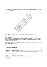
1. Attach the transmitter to the camera, taking the placement recommendations into account.

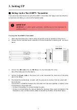
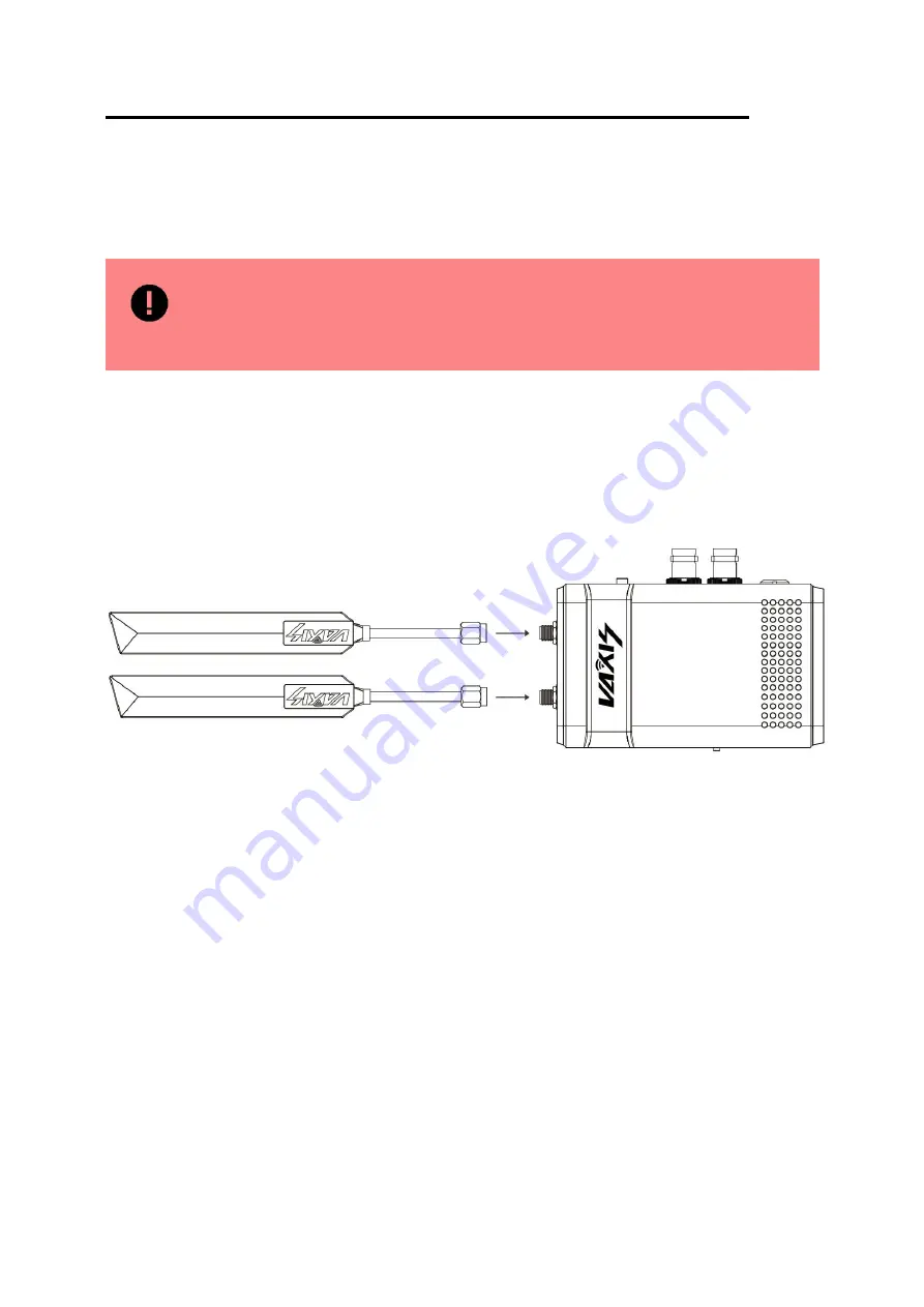
2. Connect the two provided sword antennas to the two transmitter’s antenna ports, as shown

below:

3. Connect the

SDI cable

from the

SDI IN

port on the transmitter,The other

side of this cable goes into the camera.

4. Connect the

Power cable

to the power port on the transmitter.The other side of this cable

goes to the battery.

5. The transmitter automatically connects with the powered on receiver that are paired with

this transmitter.

A connection is established between the transmitter and receiver regardless of whether video

is transmitted on the wireless link:

• If video is transmitting, the receiver display the video.

• If video is not transmitting, the receiver display the message: Video signal not detected. The

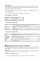
transmitter’s video and transmission status is indicated by its LEDs, as described below.

Summary of Contents for Thor 800FT+

Page 1: ......

Page 2: ...Vaxis Thor 800FT Wireless Transmission System User manual 1 Cautions 1 2 About 2 3 Setting UP 5 4 Placement Guidelines and Best Practices 10 5 Operation instruction 11 6 Maintenance 17...

Page 3: ...product in the extreme hot cold dusty or humid environments Prevent friction with hard objects Avoid the product falling down from a high place or it may damage the hardware The product is not water p...

Page 4: ...the receiver also provides a 3G HD SDI output and a HDMI output The wireless HD suite has 2 sword antennas in transmitter side and 3 sword antennas in receiver side and it can work in 5 1 5 9GHz freq...

Page 5: ...ord antennas in transmitter side and 3sword antennas in receiver side Mounting Transmitter side with Sony NP 970 plate Receiver side with V mount Gold mount plate Support metadata timecode and start s...

Page 6: ...measurements link quality and battery status Encryption AES 128 RSA 1024 for key exchange Operating Temperature 0 45o Celsius Regulation Chinese regulation supported Camera Unit Monitor Unit Video Int...

Page 7: ...wo transmitter s antenna ports as shown below 3 Connect the SDI cable from the SDI IN port on the transmitter The other side of this cable goes into the camera 4 Connect the Power cable to the power p...

Page 8: ...resolution that is not supported by the Transmitter For a list of sup ported resolutions Transmitter Signal LED Solid A link has been established to the Receiver meaning that video is being transmitte...

Page 9: ...7...

Page 10: ...via SDI by connecting a standard SDI cable from the Receiver s SDI port to the monitor s SDI port 3 Enable display of the received video via HDMI by connecting a standard HDMI cable from the Receiver...

Page 11: ...ly a system error has been detected In this case contact VAXIS support The behaviors of each individual LED are described in the tables below Receiver Video LED Solid The video signal from the camera...

Page 12: ...le a brick wall will cause more interference that a thin drywall For more placement guidelines and best practices refer to Placement Recommendations for Transmitter and Receiver Placement Recommendati...

Page 13: ...s refer to Acti vating the Information Bar Various alerts and notifications For more information refer to Alert and System Messages You can perform the following activities from the OSD menus Check da...

Page 14: ...he OSD joystick is made up of four direction selectors Up Down Left and Right and a confirmation button in the center Enable On Screen Display by pressing the confirmation button The Main Menu screen...

Page 15: ...formation Bar The Info Bars menu option determines whether or not the Information Bar is overlaid on the video received from the Transmitter Toggle the option between OFF and ON by pressing the Right...

Page 16: ...m to perform as expected the firmware version in the Receiver and the Transmitter must be the same Alert and System Messages The tables below describe messages that may appear on the monitor connected...

Page 17: ...to Multiple Monitor Units Multicasting to Multiple Receivers A single Transmitter can transmit video downlink to up to 4 Receivers This is called multicasting The following procedure describes how to...

Page 18: ...ter with which to pair this Receiver It is assumed that the Transmitter has already been set up as described in Setting Up the Thor 800FT Transmitter 4 Press and hold the Transmitter s Reg button for...

Page 19: ...C 60 C For long time storage requirement please use original carbon boxes and avoid from high humid acid base or dusty place Maintenance Warning To ensure your safety place choose well known brand DC...

Page 20: ......

Reviews: