VARSITY Scoreboards 3314 Installation Manual Download Page 8

8

PRODUCT SPECIFICATIONS

CONSTRUCTION

22-gauge galvanneal steel cabinet with powder coat finish for strength, 

durability, and lasting appearance

INSTALLATION RECOMMENDATIONS

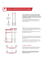
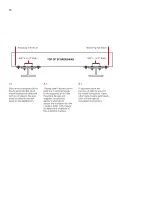
We recommend this model to be installed between (2) 8” steel I-beams 

(W8 x 13). 

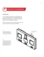
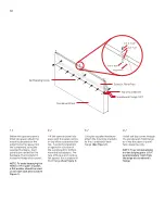
Total length determined by local codes, customer preferred mounting 

height, and scoreboard options. Concrete Footer depth /diameter as 

well as pole/concrete specifications must be based on customer’s local 

building codes, soil conditions, and wind loads. Flat Stock mounting 

brackets and bolts are supplied.  

Support structure and mounting hardware supplied by installer/others.
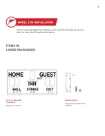
OVERALL DIMENSIONS

8’ L x 4’ W x 8” D - shipped in one (1) section 

WEIGHT

Hanging weight = approximately 150 lbs 

Shipping weight = approximately 180 lbs

POWER REQUIREMENTS

SCOREBOARD

(1) 20-amp, 120-volt, 60-hertz, grounded AC circuit, disconnect switch at the scoreboard is 

recommended. Specific power requirement information is also marked on the scoreboard’s serial 

number label, located on the scoreboard. Power consumption is 72 watts.

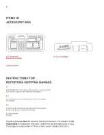
LCD WIRELESS KEYBOARD CONTROLLER

(1) 12-volt adaptor in a standard 120V outlet to charge the controller

NOTE: To maintain the life of the LCD controller, in between games or seasons, store the keyboard in 

a place where you can keep the adapter plugged in year-round, helping regulate the battery voltage.

Summary of Contents for 3314

Page 1: ...MODEL 3314 Installation Manual HOME BALL STRIKE OUT GUEST INN 3314...

Page 2: ...for the period specified in the warranty from the date of invoice SERVICE Technical Support is available 24 hours a day 7 days a week 1 800 411 3136 https www varsityscoreboards com support contact s...

Page 3: ...stalling this scoreboard for a client please return the manual to the individual in charge of the scoreboard upon completion of installation SCOREBOARD DIMENSIONS 8 0 wide x 4 0 tall x 8 depth A NOTE...

Page 4: ...ALLATION OVERVIEW 7 PRODUCT SPECIFICATIONS 8 DETERMINING LOCATION AND ORIENTATION 9 INSTALLING MOUNTING POLES OR I BEAMS 10 MOUNTING THE SCOREBOARD 11 12 INSTALLING SPONSOR PANELS 13 14 TESTING INSTAL...

Page 5: ...ball Scoreboard Shipped in 1 section Please inspect all shipping containers upon arrival for damage and ensure that you have all of the parts listed below ITEMS IN LARGE PACKAGE S Mounting Tools Flat...

Page 6: ...that aren t sighted for as damaged upon arrival The shipper is responsible for filing a claim unless shipped 3rd party 1 Note DAMAGED on the Delivery Receipt Form including details of the type of dama...

Page 7: ...tion applies to all Follow this guide as closely as possible to ensure proper installation 1 Review the product specifications below to determine your specific installation hardware 2 Determine the sc...

Page 8: ...d mounting hardware supplied by installer others OVERALL DIMENSIONS 8 L x 4 W x 8 D shipped in one 1 section WEIGHT Hanging weight approximately 150 lbs Shipping weight approximately 180 lbs POWER REQ...

Page 9: ...d the system be used to score a daytime or afternoon game The scoreboard should be positioned so that sunlight does not glare off its face In the U S placement on the South or West side of the field i...

Page 10: ...low Remember Keep boom and lines away from power lines to avoid shock or electrical burn 2 The poles I beams must be set into concrete footers Make sure the poles are level and plumb and spaced on rec...

Page 11: ...l may make servicing the scoreboard more difficult MOUNTING THE SCOREBOARD 1 Using provided hardware bolt the flat stock mounting brackets to the inside back U channel on the scoreboard 2 Using the li...

Page 12: ...drill the mounting flanges and supports to use bolts washers and nuts to secure the scoreboard to the I beams Refer to the figure for detailed illustrations of this mounting method TOP OF SCOREBOARD...

Page 13: ...G SPONSOR PANELS NOTE DETERMINE NUMBER OF SPONSOR PANELS BEING INSTALLED AND THEIR LOCATION 3 Mounting Brackets 6 3 8 16 x 3 4 Bolts 12 M3 8 Flat Washers 6 3 8 16 Hex Nuts 9 8 x 1 2 Self Tap Screws 1...

Page 14: ...for top mounted installations or against the bottom of the scoreboard for bottom mounted installations The face of the panel should be flat against the scoreboard s front flange See Figure 1 3 Using...

Page 15: ...e screen will display Segment Test and Segments Off Press the down arrow once to display Segments On When all segments are on all digits should display 8 4 Press the down arrow again to display Digits...

Page 16: ......

Reviews: