


S
2.9.7
F
c
2
C
Safety infor
The rele
is opera
pump”,
Assumin
ensure t
occur in
pumped
(e.g., du
7 Maintena
For safe and
condition. Th
The actu
conditio
caused
Regular
auxiliary
proper f
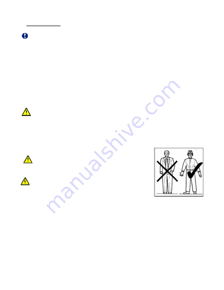
2.9.8 Safe
Wear ap
Avoid l
get cau
meets
hearing
Do not
not com
couplin
parts. D
CAUTION!
S
t
rmation:
evant admis
ated at a hig
contact the
ng an ambie
that temper
n the event o
d medium. O
ue to evapo
ance
d reliable o
his also app
ual service
ons on site.
by overhea
rly monitor v
y systems a
functioning.
ety and acc
ppropriate c
loose garme
ught in mov
safety regu
g protectors
t perform an
me close wi
ngs, etc.) D
Do not step
Switch the
the plant.
ssible opera
gher temper
manufactu
ent tempera
rature class
of an insuffi
Operating th
oration in the
operation, m
plies to the f
life of the a
Regular che
ated bearing
vibration be
are installed
cident preve
clothing whe
ents with loo
ving compon
ulations: glov
s and helme
ny maintena
ith your han
o not come
p on the mot
motor off
ating tempe
rature and n
rer for the m
ature of 40°
s T4 is main
iciently filled
he pump ou
e interior).
make sure t
function of t
antifriction b
ecks of the
gs, start-up
ehaviour to e
d, check to s
ention stan
en working
ose parts (t
nents. Wear
ves, insulat
et (see figur
ance work w
nds to any m
e close with
tor pump to
in case of
Page
11
rature of the
no data she
maximum a
°C, grease l
tained for th
d interior, b
utside the ad
the unit is p
the antifrictio
bearings dep
running no
of the exter
ensure the
see whethe
ndards
in the vicini
ies, scarves
r protective
ting footwea
re on the rig
with the mot
moving parts
your hands
o perform in
emergency
e pump is in
eet is availa
dmissible o
ubrication a
he antifrictio
ut also in th
dmissible ra
properly ser
on bearings
pends on th
ise prevent
rnal rotor on
proper func
r monitoring
ty of the pu
s, etc.) that
clothing tha
ar, goggles,
ght).
or running.
s (e.g. belts
s to hot mot
terventions
y. Inform th
ndicated in
ble or the p
operating te
and proper
on bearings
he presence
ange may a
rviced and
s.
he mode of
the risk of
n the lanter
ctioning of th
g facilities s
mp.
could
at
Do
s,
tor
.
he personn
the data sh
pump is use
mperature o
maintenanc
s. Dry-runni
e of high ga
also lead to
kept in per
operation a
excessive t
n or defecti
he plain bea
should be in
nel respons
heet. If the p
d as a “poo
of the pump
ce and oper
ng may not
s contents
dry-running
rfect technic
and the spec
temperature
ve bearing
arings. If
nstalled to e
sible for
pump
ol
p.
ration,
t only
in the
g
cal
cific
es
seals.
ensure
Summary of Contents for V 100-2
Page 1: ...Operating Manual V Series Internal Gear Pumps with Magnetic Coupling ...
Page 34: ...Page 34 ...
Page 35: ...Page 35 ...