Vario Systems Osprey 460e Installation Manual Download Page 11

Osprey 460e AV Option Installation Guide 

Osprey 


Connecting to the optional panels 

The optional panels include the cables that connect to the A/V option connectors or the Osprey 
460e or 450e video capture card and a standard 19-inch rack panel. Cables are removable from the 
panels. 

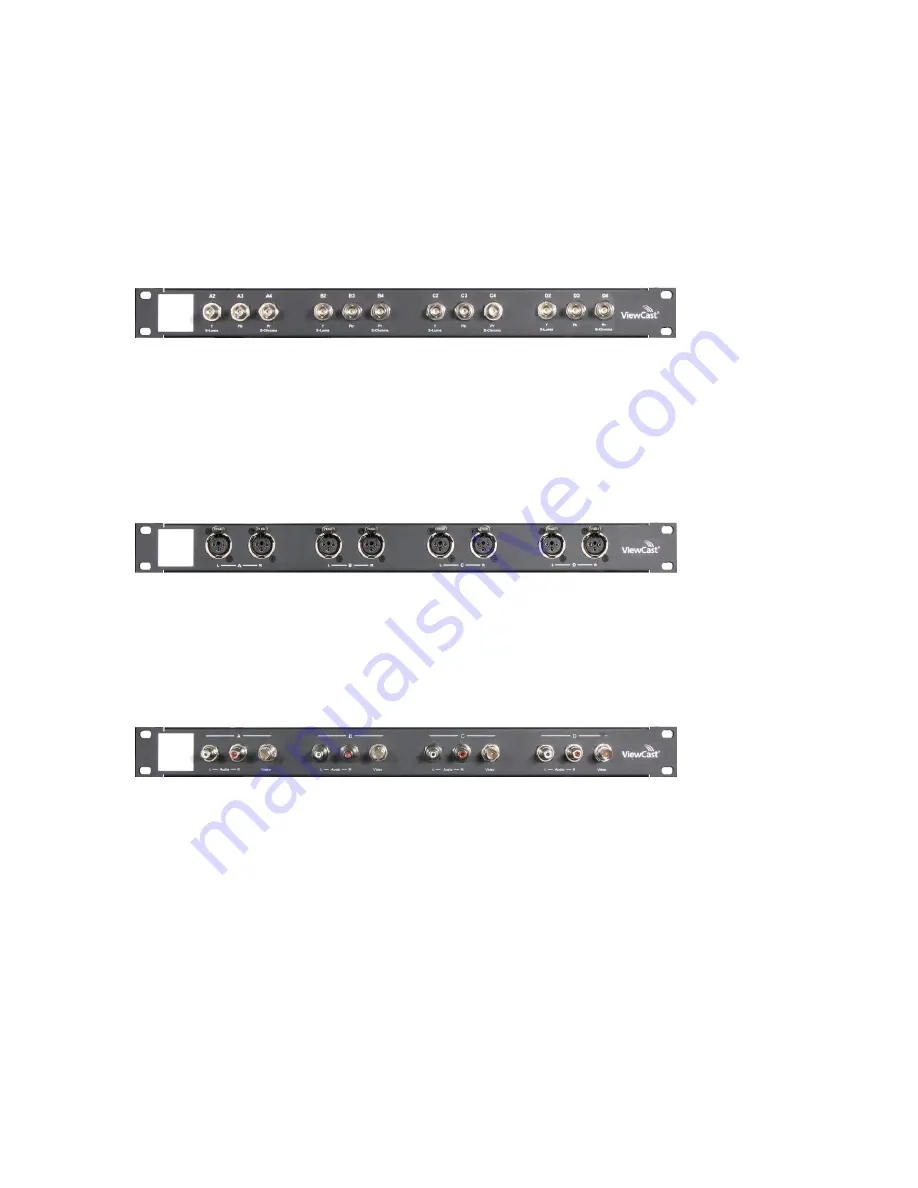
Figure 11. 95-00463 Osprey 460e Component Video Panel 


On the Component panel, Composite 2, Composite3 and Composite4 are indicated by A2, A3, and 
A4 for the A channel. Composite1 (A1) would be the physical input on the bracket of the Osprey 
460e video capture card. Y/C (S-Video) is indicated by S-Luma and S-Chroma. Component is 
indicated by Y, Pb and Pr. 


Figure 12. 95-00462 Osprey 460e Balanced Audio Panel 


The balanced audio panel brings out 4 stereo pairs of balanced audio from the A/V option DB25 
connector. 


Figure 13. 95-00460 Osprey 460e/440 Breakout Panel 


The Osprey 460e/440 breakout panel extends the connector on the Osprey 460e, 450e, or 440 video 
capture card to the panel. This includes the 4 composite video connectors (BNC) and the 4 pairs of 
unbalanced stereo audio (RCA) from the breakout cable. 


Summary of Contents for Osprey 460e

Page 1: ...Osprey 460e A V Option Installation Guide...

Page 2: ...levision reception the user is encouraged to try to correct the interference by one or more of the following measures Reorient or relocate the receiving antenna Increase the separation between the equ...

Page 3: ...of the 4 channels or 3 additional composite inputs for a total of 12 composite inputs per video capture card Osprey provides the following cable panel options for the A V option 95 00459 Osprey 460e A...

Page 4: ...r and it is TASCAM DTRS compatible Figure 3 A V Option Board Front View DB25 DB 25 Pinouts Pin Description Pin Description 1 D Right 14 D Right 2 D Right Shield 15 D Left 3 D Left 16 D Left Shield 4 C...

Page 5: ...A Pr A S Chroma 2 B3 B Pb 3 C2 C Y C S Luma 4 C4 C Pr C S Chroma 5 D3 D Pb 6 A3 A Pb 7 B2 B Y B S Luma 8 B4 B Pr B S Chroma 9 C3 C Pb 10 D2 D Y D S Luma 11 A2 A Y A S Luma 12 Shield Gnd Shield Gnd Shi...

Page 6: ...erforming these steps To connect the A V option 1 Locate Audio pin 1 on the Osprey 460e card Figure 4 Figure 4 Osprey 450e Video Capture Card 2 An arrow is located at one end of the ribbon cable Figur...

Page 7: ...te Assembly Note The recommended procedure is to install the driver software prior to installing the Osprey video capture card in the computer As soon as you install an Osprey card in the PC the card...

Page 8: ...on Installation Guide Osprey 6 Figure 8 PCI Express Slot 10 Power up the computer The OS will detect the newly present Osprey card and begin to activate the driver 11 When the installation is complete...

Page 9: ...addition of the A V option and component panel the Osprey AVStream Driver enables you to select any of these as physical inputs to each channel As an example the driver lists Osprey 460 Device 1A 1B 1...

Page 10: ...wn list to display all of the available video inputs for channel A Composite1 Composite2 Composite3 Composite4 Y C S Video and Component Note The Osprey 460e can capture video from only one of the fou...

Page 11: ...channel Composite1 A1 would be the physical input on the bracket of the Osprey 460e video capture card Y C S Video is indicated by S Luma and S Chroma Component is indicated by Y Pb and Pr Figure 12 9...

Page 12: ...mulStream are registered trademarks of Osprey by Variosystems LLC or its subsidiaries All other trademarks are the property of their respective owners Product specifications and availability may chang...

Reviews: