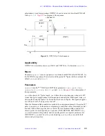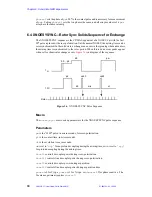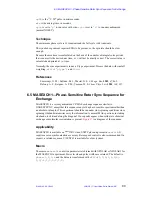
Chapter 5. Solid-State NMR Accessories
75
VNMR 6.1C User Guide: Solid-State NMR
01-999162-00 C0402
Using Rotor Synchronization
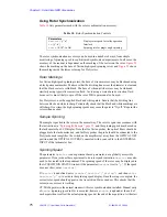
lists parameters used with the rotor synchronization accessory.
The rotor synchronization accessory can be used in a number of ways, from simple
monitoring of spinning speed to sophisticated synchronized experiments. In all cases, the
accuracy of the readout is dependent on the marking of the sectors on the rotor.
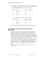
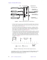
shows the marking on the base of Varian high-speed spinning rotors and
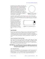
shows
the marking inside the lower rotor cap for Doty rotors.
Rotor Markings
For Varian high-speed spinning rotors, the base of zirconia rotors may be blackened using
a black permanent marker. Make sure that the dividing line across the diameter is clear and
that the black sector is solid black. The base of silicon nitride rotors may be whitened
similarly using typewriter correction fluid. Avoid using a water-based correction fluid
because it is more likely to spin off the rotor. White paint can also be used.
For Doty rotors, use the supplied black and white paints. Ensure that the dividing line
between black and white is sharp. Periodically check that the black and white markings are
still sharp. Over time, the high spinning speeds may cause the paint to “fly off.” Repaint the
rotors when needed.
Sample Spinning
The sample is packed in the rotor in the normal way. The rotor is spun in accordance with
the instructions in
“Spinning the Sample,” page 22,
and the spinning speed may be read on
the tachometer box LCD display. Note that for Varian probes, the optical fibers should be
plugged into the tachometer box, and for Doty probes the probe should be connected to the
Doty tachometer amplifier, the switch on the amplifier set away from the OPTICAL OFF
position, and the OPTICAL OUT BNC connected with a coax cable to the EXTERNAL
INPUT of the tachometer box.
Spinning Speed
The parameter
hsrotor
is an experiment-based parameter, not a globally accessible
parameter. If you join another experiment to do rotor synchronization,
hsrotor
may also
need to be created in that experiment. The spinning speed of the rotor may be displayed in
the ACQUISITION STATUS window if the parameter
hsrotor
is set to
'y'
. If the speed
does not show, enter
hsrotor?
If
hsrotor
is undefined, enter
create('hsrotor','string')
, and then
enter
hsrotor='y'
su
to activate the spinning speed display. Once the setup is complete, the
correct rotor speed should appear in the Acquisition Status window. This checks that the
rotor sync accessory is working.
CP/MAS operates in the normal manner with rotor synchronization installed. Manual entry
of
srate
(spinning speed in Hz) is accepted; however,
srate
is updated at the end of
each acquisition to reflect the actual spinning speed at the end of the acquisition. At the start
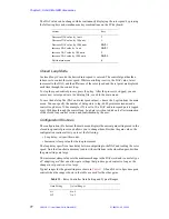
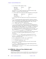
Table 10. Rotor Synchronization Controls
Parameters
hsrotor
{'y', 'n'}
Display rotor speed for solids operation
in
{'y', 'n'}
Interlock
srate
{0–107, in Hz}
Spinning rate for magic angle spinning


