


INSTRUCTION MANUAL
·
MIG SERIES
9
6.2.3 Operation
(1) Turn the power switch on the back panel to “ON” position after the installation according to
the above steps, the machine is started, the power LED turns on, and the fan works.
(2) Turn the conversion switch on the front panel to “MMA” position, and adjust the welding
current adjustment knob according to the workpiece thickness to get the desired welding
performance.
(3) Generally, the required welding current is listed as follows:
Ф
2.5: 70-100A;
Ф
3.2: 110-160A;
Ф
4.0: 170-220A;
Ф
5.0: 230-280A
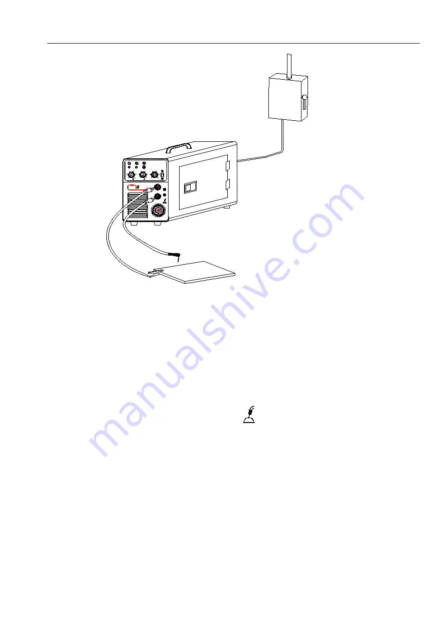
6.3.1 Installation of gas shielded arc welding
(1) Plug the welding torch into the output socket “
” on the front panel, and tighten it. Thread
the wire into the torch manually.
(2) Insert the earth cable plug into the negative socket “1” on the front panel, and tighten it
clockwise.
(3) Insert the fast plug on the wire feeder into the output socket
“
GAS
”
on the clapboard, and
tighten it clockwise.
(4) Fix the welding wire coil to the rack axis on the wire feeder; make sure the hole of the wire
feeding wheel matches well with the bolt on the rack axis and the welding wire diameter.
Unfasten the screw on the wire-pressing wheel, and make the wire into the glove of the
wire feed wheel, press the wire tightly, but not too tight, and then thread the wire into the
torch. Press the” wire feeding” button to feed the wire out of the welding gun.
(5) Tightly connect the gas hose, which come from the back of the machine to the copper
nozzle of gas bottle.
MIG 160
J35
Switching box