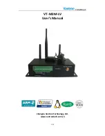
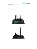


VT-M2M-LV
10
/
21
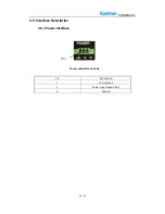
3.2
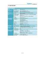
Specifications
Specifications
CPU
Processor
ARM9 processor
Memory
On Board RAM
DDR2 128MB(64Meg x 16)
ROM Internal
NAND 128MB (256MB or others)
Wireless
Communicati
on
WLAN
Optional 1X802.11/ b/g/n Wireless Module
external antenna
3G/4G Primary&
4G Secondary
Optional 1x mini PCIE 4G or 3G Broad Band Module
with SIM slot
GPS
Optional 1X GPS module, external antenna
ZigBee
Optional, or RF 2.4G
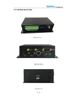
Peripheral
Interfaces
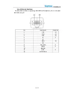
Ethernet
1x10/100M-BaseT(RJ45)
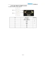
COM Port
1xDB9 RS232/485
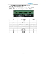
1xRS232/485/422
1xCAN 2.0b up to 1Mbit/s
Alarm
Buzzer Out
SD card
1xSD card Slot (Optional )
RTC
Supported
GPIO
Reserved GPIO X4(Terminal)
Security
Security(Option
al)
On board Registration Serial Number, and SHA-1
Encrypt/Decrypt Chip DS28E01
Power
Input
DC6-36V(default 12V), Locked Power Jack
Consumption
TBD
Environment
Condition
Temperature
Operating:-20°C ~ +70°C
( ETR:-40°C ~ +80°C Optional)
Storage: -40°C ~ +85°C,
Humidity
5-95%RH at 25-35 (Non-Condensation)
Cooling Mode
Fan less, Heat Sink
Approvals
UL, FCC Class B, and CE


