


~ 13 ~
COM3000 Integrator’s
Installation Manual
Date: January 2024
Version 1.1
6
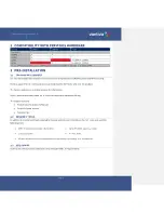
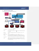
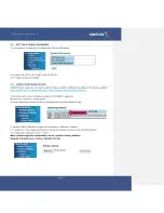
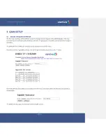
SYSTEM POWER UP
Once assembled and connected to RF distribution power up the COM3000 by plugging in the power cord. There
is no external power switch.
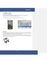
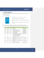
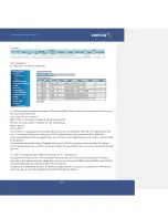
System startup LED Behavior
The COM51 card has 6 LEDs on the front panel the top three are:
PWR
–
Displays solid green when the card is powered.
Activity
–
Flashes green when there is Ethernet activity between the chassis
and card.
Link
–
Displays solid green indicating the card has Ethernet link to the chassis
backplane.
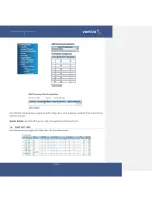
Upon powering up the COM51 cards LEDs will go through a series of flashing indicating boot up.
Error! Reference source not found.
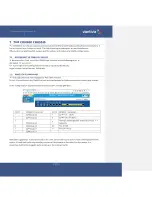
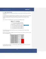
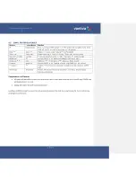
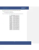
The table below describes the LED activity during boot and normal operation.
LED 1
LED 2
LED 3
Stage
Note
OFF
OFF
OFF
Power Off
Normal Boot
ON
OFF
OFF
Power On
Normal Boot
OFF
ON
OFF
Checking imageA signature
Normal Boot
ON
ON
OFF
Checking imageB signature
Normal Boot
OFF
OFF
ON
Booting ImageA
Normal Boot
ON
OFF
ON
Booting ImageB
Normal Boot
OFF
ON
ON
Failsafe downloading image. Card will
attempt TFTP download from
192.168.1.254. COM51.bin. Using
external TFTP software.
Fail Safe Mode
FLASH
OFF
OFF
Failsafe image download failed, reboot
after 10 seconds
FATAL ERROR
OFF
FLASH
OFF
Failsafe image invalid, reboot after 10
seconds
FATAL ERROR
OFF
OFF
FLASH
Programming failsafe image into flash
failed
FATAL ERROR
ON
ON
ON
Failsafe flash programming
Fail Safe Mode