Installation and Start-up
IT SERIES Industrial True Sine Wave Inverter Owners Manual
23
Remote Control Wiring Installation
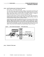
1. Refer to the wiring sketches found in the Component Identification and Description of Operation
section, item (32), Remote Control Terminal Block. Use fuses where indicated.
2. Use cable clamp provided to secure wiring. A plastic plug is provided for the unused opening.
AC Output Wiring Installation Procedure
WARNING: Before proceeding with the AC wiring, verify that the inverter is OFF and that the
inverter is NOT connected to the battery. Serious or fatal electrical shock may occur.
1. The wiring of your inverter installation should conform to the National Electric Code (NEC) and any
other state or local codes in effect at the time of installation. These codes have been written for your
protection and their requirements should be followed
2. Route the AC output wiring, and DC power wiring, with as much physical separation as possible from
low voltage wiring such as audio and video signal wires.
3. Remove the right front cover to expose the AC wiring compartment and the AC Output Wiring
Terminal Block. Output Circuits AC-1 and AC-2 are identified on the terminal block label and are
defined in Section 2, items 16, 17 and 20.
4. A cable clamp is provided to secure the AC output wiring. A plastic plug is provided to plug the
unused opening.
5. Verify AC wiring installation. Verify that all connections are tight. Secure all wiring.
Start-up and Test Procedure
After the inverter has been properly mounted with sufficient ventilation, DC cables have been connected
to the inverter (but not yet to the battery), AC wiring has been completed, and all remote connections
have been checked; the Start-up and Testing procedure should be performed.
WARNING: These procedures are to be performed only by a QUALIFIED INSTALLER.
Inverter Start-up and Testing
1. Place the Inverter ON/OFF switch in the OFF position.
2. Place any remote switches in the OFF position.
3. Verify that any external AC output circuit breakers and GFCI receptacles are reset.
4. Connect the battery to the inverter. BE AWARE, as a quantity of capacitors become charged upon
completing the DC circuit, THERE WILL BE A LARGE SPARK when the last connection is made.
5. Turn the inverter ON and use a test load (75 watt trouble light) plugged into the 15 amp GFCI
receptacle to verify the inverter produces AC power.
6. Refer to the description of operation of the indicator lights, Section 2, items 4 through10 to follow and
verify correct inverter operation.
7. If the inverter is not operating as described, see Trouble Shooting Procedures


