
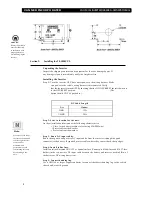


VANNER INCORPORATED
20-1050CUL INVERTER/CHARGER—OWNER'S MANUAL
2
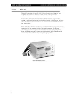
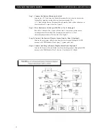
FUNCTIONALITY
Inverter
The 20-1050CUL converts battery power to 1050 Watts of 120 VAC modified sine wave
power to operate vital emergency vehicle equipment. The unit is easily connected to the
positive and negative posts of a battery system with appropriate fusing, and when turned
on produces 120 VAC True RMS power.
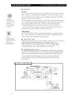
The inverter also has an energy-saving feature called Load Demand. With this feature the
inverter output is pulsed significantly reducing the current draw from the battery until a
demand is made on its output. Continuous output of 120 VAC resumes when a load greater than 5
Watts is applied. The load demand feature can be disabled with the Setup Switch on the front panel.
A built-in transfer relay switches the AC output receptacle from the inverter to the AC
input when the unit senses AC input from the shore/utility power.
Battery Charger
The 20-1050CUL Battery Charger's superior design incorporates a multi-stage charger.
This design enables the unit to automatically charge batteries, maintaining the battery's
integrity and reducing the likelihood of premature failure.
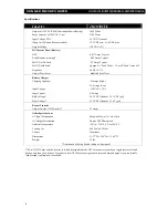
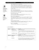
H i g h C h a r g e M o d e
While in the High Charge mode, the unit continuously charges at a constant current of 55
Amps (high setting) for large battery banks, or 15.0 Amps (low setting) for
small battery banks (such as two group 31 batteries). The unit will charge until the
battery cells reach 14.2 VDC for flooded batteries. or 19.1 VDC for gel batteries.
The unit then supplies a fixed voltage until the battery is fully charged.
R e a d y/ M a i n t e n a n ce M o d e
The charger automatically enters the Ready/Maintenance mode, maintaining the battery's proper
voltage of 13.2 VDC for flooded batteries or 13.6 VDC for gel batteries. This Ready/Maintenance
mode is designed to eliminate gassing (overcharging), helping to extend the life of the battery.
A Setup Switch is located on the front panel for selecting the type of battery (Flooded
Lead Acid or Gel Lead Acid), the battery charger output current (High/Low), and Load
Demand(On/Off).
WARNING
Battery input cables
must be connected to
the battery
with proper polarity
to avoid damaging
the inverter.
NOTE
If the battery is fully
charged at the time AC
input is applied, the unit
will go
directly into Ready/
Maintenance mode.
Summary of Contents for 20-1050CUL
Page 1: ......


