Vanner 20-1000TUL Owner'S Manual Download Page 9

Vanner Power Group

20-1000TUL INVERTER—OWNER'S MANUAL
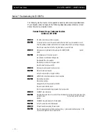
Section 4:

Installing the Inverter Remote Status Display Panel

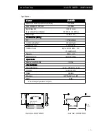
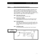
The Inverter Remote Status Display Panel (p/n D06638) contains separate, red and
green LED indicators. The green indicator light signifies the inverter is On or in
Standby mode. The red, Fault LED indicator shows problems such as over tempera-
ture, output overload, or low battery. The panel has a sealed overlay which mounts
easily on a flat surface. A 12-in. pigtail harness is included for easy installation. Use the
following procedure to install the Inverter Remote Status Display Panel.

Step 1: Select a location for the panel.

Identify the desired location for the inverter panel.

Step 2: Identify wires for installation.

Identify the gray, green, and red wires on the inverter panel and vehicle's

electrical system wires that will connect to the IFM1 Interface Module.

Step 3: Splice and arrange wires.

Splice together like-colored wires from the vehicle's electrical system to the

status panel using an insulated butt splice or equivalent. Carefully arrange the
wires such that the panel mounts flush against the surface to which it is
mounted.

Step 4: Secure panels to surface.

Mount the panels using #8 screws through the four holes in the panel.
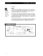
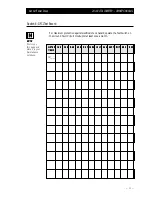
FIGURE 2—

IFM1 MODULE

REMOTE WIRING

— 7 —

Summary of Contents for 20-1000TUL

Page 1: ...Model 20 1000TUL AC Power Inverter System OWNER S MANUAL OM A96751 REV A...

Page 2: ...he 20 1000TUL Inverter 9 Section 7 Troubleshooting 10 Section 8 GFCI Test Record 11 Warranty 12 List of Figures Figure 1 System Diagram 2 Figure 2 IFM1 Module Remote Wiring 7 Icon Legend W W W W Warni...

Page 3: ...lent performance and reliability for your emergency vehicle With minimum maintenance and care you can expect years of trouble free service from your Vanner product The 20 1000TUL is a 12 VDC to 120 VA...

Page 4: ...tly reducing the current draw from the battery until a demand is made on its output Continuous output of 120 VAC resumes when a load greater than 5 Watts is applied The load demand feature can be disa...

Page 5: ...ry y y y y OFF 0 017 Amps Typical Load Demand waiting 0 09 Amps Typical Full ON at No Load 0 7 Amps Typical Full ON with Load Approx AC Load Watts 10 or AC Load Amps x 12 Frequency 60 Hz 0 1 Output Wa...

Page 6: ...rom the weather Well ventilated Step 3 Route DC input cables Route the negative and positive DC input cables from the inverter through the quick connector to the battery If required protect cables whe...

Page 7: ...ht Action Light Action Description Description Description Description Description Solid Red Inverter is On and the battery is almost too low to operate the inverter Blinking Red The inverter is Off T...

Page 8: ...ce Cable length to the inverter Additionally the unit should not be installed with pin connections facing upward Step 2 Connect the Inverter to the Interface Module Install the 2 ft interface cable by...

Page 9: ...re to install the Inverter Remote Status Display Panel Step 1 Select a location for the panel Identify the desired location for the inverter panel Step 2 Identify wires for installation Identify the g...

Page 10: ...is operational Single Blink Green Light Inverter is not being used Shore power is applied to load Inverter will activate when shore power is unavailable Double Blink Green Light Inverter is on in the...

Page 11: ...the ON position When powered by the AC power the ON lamp flashes indicating that the inverter is standing by Step 5 Verify Power Apply an AC load such as a shop light or drill The AC load is run dire...

Page 12: ...ower is OFF SYMPT SYMPT SYMPT SYMPT SYMPTOM OM OM OM OM ON lamp fully illuminates AC load does not run SOL SOL SOL SOL SOLUTION UTION UTION UTION UTION Check and reset circuit breaker Verify AC load a...

Page 13: ...L J U L J U L J U LY Y Y Y Y A U G A U G A U G A U G A U G S E P T S E P T S E P T S E P T S E P T O C T O C T O C T O C T O C T N O V N O V N O V N O V N O V D E C D E C D E C D E C D E C Y E A R Y...

Page 14: ...ts product for any undertaking representation or warranty made by any dealers or distributors selling its products beyond herein expressed 5 Vanner does not assume responsibility for incidental or con...

Page 15: ......

Page 16: ...nner Power Group ower Group ower Group ower Group ower Group 4282 Reynolds Drive Hilliard Ohio 43026 Tel 614 771 2718 Fax 614 771 4904 Specifications Subject to Change Copyright 1996 Vanner Weldon Inc...

Reviews: