background image

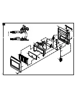
30

100100

ODS/Pilot

1

2

3

4

5

6

7

8

9

10

10

11

12

13

14

15

16

17

19

27

21

23

24

25

26

22

29

28

20

30

18

12-1

12-2

Summary of Contents for VGP30B

Page 1: ...or use gasoline or other flammable vapors and liquids in the vicinity of this or any other appliance WHAT TO DO IF YOU SMELL GAS Do not try to light any appliance Do not touch any electrical switch d...

Page 2: ...monoxide poisoning WARNING ICON G 001 DANGER Carbon monoxide poisoning may lead to death Carbon Monoxide Poisoning Early signs of carbon monoxide poisoning resemble the flu with headaches dizziness or...

Page 3: ...pilot light safety system The ODS shuts down the heater if not enough fresh air is available See Fresh Air for Combus tion and Ventilation pages 5 through 8 7 Never run heater in small closed room 8...

Page 4: ...s a piezo ignitor This system requires no matches batteries or other sources to light heater UNPACKING 1 Remove heater from carton 2 Remove all protective packaging applied to heater for shipment 3 Ch...

Page 5: ...The air that leaks around doors and windows may provide enough fresh air for combustion and ventilation However in buildings of unusually tight construction you must provide additional fresh air Unus...

Page 6: ...r Gas furnace ___________________ BTU Hr Vented gas heater ___________________ BTU Hr Gas fireplace logs ___________________ BTU Hr Other gas appliances ___________________ BTU Hr Total ______________...

Page 7: ...or on the wall connecting the two spaces see options 1 and 2 Figure 2 You can also remove door into adjoining room see option 3 Figure 2 WARNING ICON G 001 WARNING Rework worksheet adding the space of...

Page 8: ...en to the outdoors These spaces include attics and crawl spaces Follow the National Fuel Gas Code NFPA 54 ANSI Z223 1 Section 5 3 Air for Combustion and Ventilation for required size of ventilation gr...

Page 9: ...aces next to heater Installing heater next to vinyl or cloth wall coverings or operating heater where impurities in the air such as tobacco smoke exist may discolor walls IMPORTANT Vent free heaters a...

Page 10: ...least 18 inches above floor locate heater where moving vehicle will not hit it For convenience and efficiency install heater where there is easy access for operation inspection and service where stron...

Page 11: ...GRH OV 003B FRONT PANEL REMOVAL G H Figure 6 Removing Front Panel Of Heater Methods For Attaching Mounting Bracket To Wall Only use last hole on each end of mounting bracket to attach bracket to wall...

Page 12: ...G TO WALL Continued Attaching Mounting Bracket To Wall Note Wall anchors mounting screws and spacers are in hardware package The hardware package is provided with heater Attaching to wall stud method...

Page 13: ...talling Bottom Mounting Screws 1 Locate two bottom mounting holes These holes are near bottom on back panel of heater see Figure 11 2 Mark screw locations on wall 3 Remove heater from mounting bracket...

Page 14: ...r valves Propane Supply Tank Figure 12 External Regulator With Vent Pointing Down Vent Pointing Down External Regulator WARNING ICON G 001 CAUTION Use only new black iron or steel pipe Internally tinn...

Page 15: ...Burner bracket not shown for clarity From External Regulator 11 W C to 14 W C Pressure 3 Minimum Figure 13 Gas Connection An A G A design certified manual shutoff valve with 1 8 NPT tap is an accepta...

Page 16: ...ming show a leak 4 Correct all leaks at once PRESSURE TESTING HEATER GAS CONNECTIONS 1 Open manual shutoff valve see Figure 14 2 Open propane supply tank valve 3 Make sure control knob of heater is in...

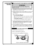
Page 17: ...e gas control knob Never use tools If the knob will not push in or turn by hand don t try to repair it call a qualified service technician or gas supplier Force or attempted repair may result in a fir...

Page 18: ...hield If needed keep pressing ignitor button until pilot lights Note If pilot does not stay lit refer to Troubleshooting pages 21 through 24 Also contact a qualified service person or gas supplier for...

Page 19: ...With control knob pressed in strike match Hold match to pilot until pilot lights 4 Keep control knob pressed in for 30 seconds after lighting pilot After 30 seconds release control knob 5 Replace fro...

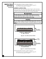
Page 20: ...icles enter the heater and burn causing brief patches of orange flame Figure 20 Correct Burner Flame Pattern Figure 21 Incorrect Burner Flame Pattern If burner flame pattern is incorrect as shown in F...

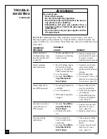
Page 21: ...roubleshooting items are listed in order of operation WARNING ICON G 001 WARNING Turn off and unplug heater and let cool before servicing Only a qualified service person should service and repair heat...

Page 22: ...problem could be caused by one or both of the following A Low gas pressure B Dirty or partially clogged ODS pilot 6 Thermocouple dam aged 7 Control valve damaged 1 Burner orifice is clogged REMEDY 1...

Page 23: ...old 2 Air in gas line 3 Air passageways on heater blocked 4 Dirty or partially clogged burner orifice REMEDY 2 Replace burner orifice 3 Contact local propane gas company 1 Contact local propane gas co...

Page 24: ...rson 1 Ventilate room Stop using odor causing products while heater is running 2 Refill supply tank 3 Locate and correct all leaks see Checking Gas Connections page 15 1 Open window and or door for ve...

Page 25: ...ater Maximum 14 14 Minimum 11 11 Dimensions Inches H x W x D Heater 23 5 x 25 9 x 8 0 23 5 x 18 5 x 8 0 Carton 25 8 x 28 7 x 10 1 25 8 x 21 3 x 10 1 Weight pounds Heater 30 22 Shipping 35 27 When gas...

Page 26: ...1 800 323 5190 for information When calling have ready your name your address model number of your heater how heater was malfunctioning type of gas used propane or natural gas purchase date Usually we...

Page 27: ...rite to the address listed on the back page of this manual FAN KIT GA3100 GA2100A Provides better heat distribution Makes heater more efficient Complete installa tion and operating instructions includ...

Page 28: ...28 100100 1 2 3 4 5 6 7 8 8 9 10 11 12 13 14 15 17 19 21 22 23 24 20 27 26 18 28 16 25 ODS Pilot 10 1 10 2...

Page 29: ...098514 01 Thermocouple 1 10 2 098594 01 Ignitor Electrode 1 11 099126 02 Burner 1 12 099387 05 3 16 Pilot Tubing 1 13 098251 05 Injector 1 14 098250 01 Injector Holder 1 15 098867 06 Pressure Regulato...

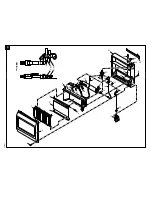
Page 30: ...30 100100 ODS Pilot 1 2 3 4 5 6 7 8 9 10 10 11 12 13 14 15 16 17 19 27 21 23 24 25 26 22 29 28 20 30 18 12 1 12 2...

Page 31: ...12 099059 04 ODS Pilot Assembly 1 12 1 098514 01 Thermocouple 1 12 2 098594 01 Ignitor Electrode 1 13 099120 02 Burner 1 14 099387 05 3 16 Pilot Tubing 1 15 098251 01 Injector 1 16 098250 01 Injector...

Page 32: ...parts that are not in original condition because of normal wear and tear or parts that fail or become damaged as a result of misuse accidents lack of proper maintenance alteration tampering contamina...

Reviews: