Check Compression Components
Compression Test
An assessment of the engine's compression components can
be made with a compression test.
1. Obtain a compression tester.
2. Remove both spark plugs.
3. Install the compression tester gauge into the the spark
plug hole of the cylinder to be tested. Refer to the
instructions included with the compression tester.
4. Turn the engine over using the starter motor until the
pressure reading on the gauge no longer increases.
5. Record the pressure reading.
6. Repeat steps 3 - 5 for the other cylinder.
With pressure readings from both cylinders, note the
difference between the two. Divide the difference in cylinder
pressure by the value of the highest pressure reading. This
indicates the difference in percentage form. A difference
of over
25%
between the cylinders indicates a loss of
compression in the cylinder with the lower pressure reading.
See example below:
Engine Compression Comparison
Engine #1
Engine #2
Cylinder #1
65 PSI
75 PSI
Cylinder #2
60 PSI
55 PSI
Difference
5 PSI
20 PSI
% Difference
7.7%
26.7 %
NOTE:
The table above is meant for use as a reference
example,
NOT
as a compression pressure specification.
Poor compression may indicate the following problem(s):
•
Loose cylinder head bolts
•
Blown head gasket
•
Burned valves, burned and/or loose valve seats
•
Warped valves
•
Valve seized in guide
•
Insufficient valve clearance
•
Warped cylinder head
•
Worn cylinder bore and/or piston rings
•
Broken connecting rods
Cylinder Leakdown Test
A cylinder leakdown test is used to check the sealing
capabilities of each cylinder. Follow the instructions for the
leakdown tester you are using for proper setup steps and
testing procedures.
1. Obtain engine leakdown tester. See
Special Tool List
.
2. Remove spark plug from engine.
3. Disconnect the crankcase breather tube.
4. Rotate the crankshaft in direction of operation until the
piston is at Top Dead Center (TDC) of the compression
stroke on the cylinder being tested.
5. Hold the crankshaft securely in place, with the piston
at TDC, to minimize the chance of rotation. This can
be done by holding the flywheel nut with a socket and
breaker bar.
6. Connect the leakdown tester to a compressed air source
with a minimum pressure of
70 psi (480 kPa)
.
7. Install the outlet hose into the spark plug hole of the
cylinder being tested.
a. Make sure that the outlet hose o-ring is seated
correctly within the spark plug hole. The o-ring is
used to prevent air leaks at the spark plug hole.
8. While holding the crankshaft securely in place, pull the
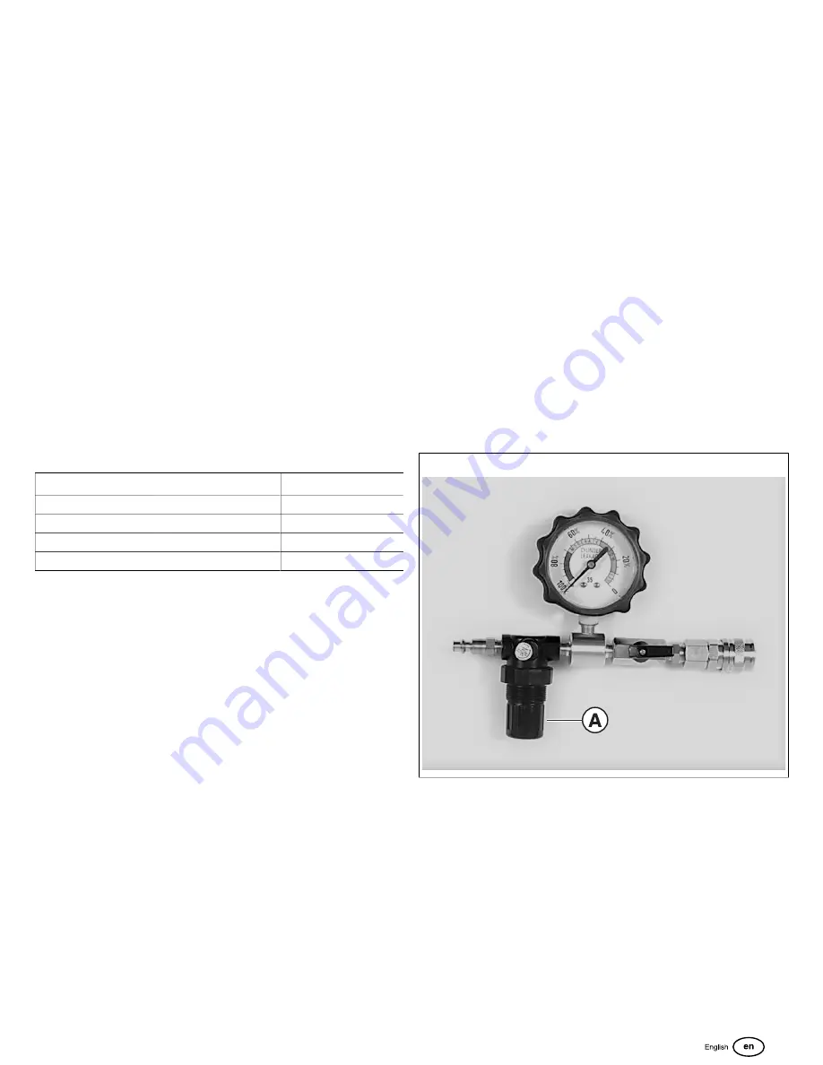
leakdown tester adjustment knob OUT (
A
, Figure 25).
Slowly turn the regulator adjustment knob CLOCKWISE
until the tester needle on the gauge is on the set point.
Push the regulator adjustment knob IN.
NOTE:
Any air leaks at the connections or fittings of the
tester will affect the accuracy of the test.
25
9. Open the tester valve slowly and note the reading
on the gauge. A drop in pressure, as read on the
leakdown tester gauge, indicates the amount leakage
of the compression components being tested. The
change, when expressed as a percentage, offers a
good indication of the condition of the cylinder being
tested.
0-10%
leakage indicates that the cylinder is good.
10-30%
leakage indicates that there may be a problem.
30-100%
leakage indicates that repairs are required.
10. Repeat steps 2 - 9 to test the other cylinder.
The sound of air flow:
•
between the cylinder and cylinder head indicates the
cylinder head gasket is leaking.
29
Summary of Contents for BIG BLOCK M540000
Page 46: ...Special Tools Image Chart 30 47...
Page 74: ...84 75...
Page 75: ...85 76 vanguardpower com...
Page 81: ...94 82 vanguardpower com...
Page 111: ...Vanguard Model 540000 145 112 vanguardpower com...
Page 113: ...Vanguard Model 610000 146 114 vanguardpower com...
Page 136: ...176 137...


