background image

Cylinder Air Guides

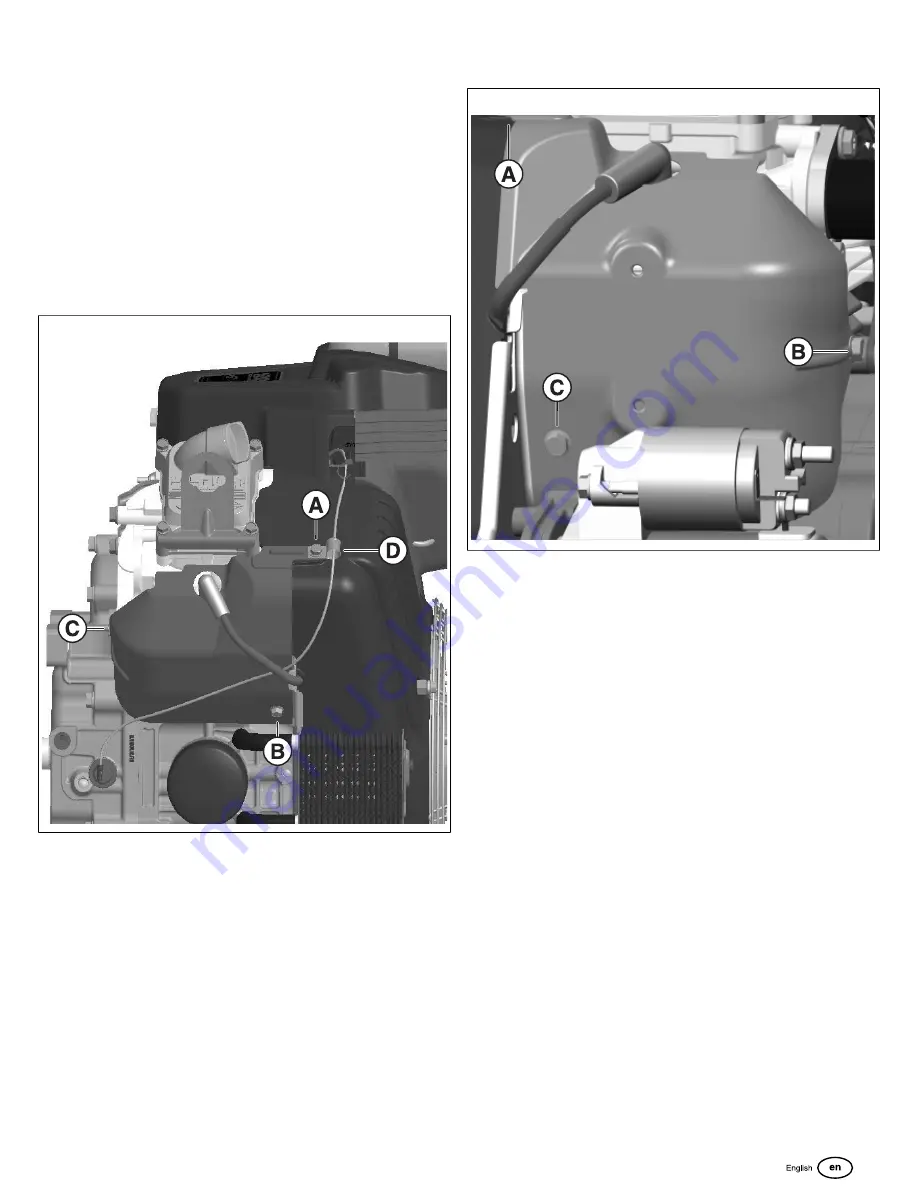
1. On the oil filter side of the engine, install the cylinder air

guide to the cylinder head. Align the air guide mounting

holes to the threaded holes in the cylinder head.

 NOTE:

 A wire routing clamp is installed on the top air guide

mount. The oil pressure switch wire is secured by the wire

clamp and the clamp is secured by the air guide mounting

fastener. Install the wire clamp and make sure that the oil

pressure switch wire is routed correctly before torqueing the

fastener.
2. Start by hand the 3 fasteners (

A, B, C

, Figure 211).

Tighten to 

90 lb-in

 (10.2 Nm).

211

 NOTE:

 A wire routing clamp (

D

) is installed on the top air

guide mount. The oil pressure switch wire is secured by

the wire clamp and the clamp is secured by the air guide

mounting fastener. Install the wire clamp and make sure

that the oil pressure switch wire is routed correctly before

torqueing the fastener.
3. On the starter motor side of the engine, install the

cylinder air guide to the cylinder head. Align the air guide

mounting holes to the threaded holes in the cylinder

head.

4. Start by hand the 3 fasteners (

A, B, C

, Figure 212).

Tighten to 

90 lb-in

 (10.2 Nm).

212

Throttle Control

Depending on your engine's model and trim, a manual

detent throttle may be equipped. For engines equipped with

a Cyclonic Air Cleaner assembly, the throttle control may

be mounted above the key switch cover at the front of the

engine. For engines equipped with a Low-Profile Air Cleaner

assembly, the throttle control may be remotely mounted. For

engine mounted throttle controls, proceed as follows. For

remote mounted throttle control, see your equipment's repair

manual for installation instructions.

153

Summary of Contents for BIG BLOCK M540000

Page 1: ...Repair Manual 80114787 Revision A BRIGGS STRATTON CUSTOMER EDUCATION Milwaukee WI 53201 USA Copyright 2023 All rights reserved VANGUARDPOWER COM Vanguard BIG BLOCK Diagnostic and Repair M540000 M61000...

Page 2: ...the data available at the time of publication Briggs Stratton reserves the right to change alter or otherwise improve the product or the product manuals at any time without prior notice Briggs Stratt...

Page 3: ...ed service parts Review the Illustrated Parts List for part availability before conducting any service work NOTE Many of the images in this document are representative of the Horizontal shaft EFI ETC...

Page 4: ...ts see SECTION 5 DISASSEMBLE ENGINE TOP END DISASSEMBLY and then proceed to SECTION 6 SERVICE ENGINE SUBASSEMBLIES CYLINDER HEAD When cylinder head service is complete see SECTION 7 ASSEMBLE ENGINE TO...

Page 5: ...CTION 3 TROUBLESHOOTING AND SPECIAL TOOLS 3 SECTION 4 REMOVE EXTERNAL ASSEMBLIES 4 SECTION 5 DISASSEMBLE ENGINE 5 SECTION 6 SERVICE ENGINE SUBASSEMBLIES 6 SECTION 7 ASSEMBLE ENGINE 7 SECTION 8 INSTALL...

Page 6: ...ATION 8 Safety Alert Symbol and Signal Words 8 Hazard Symbols and Meanings 8 General Safety Messages 8 GENERAL INFORMATION 11 Engine Identification 11 Fuel Recommendations 11 Fuel Recommendations Gase...

Page 7: ...etitive events not sanctioned by Briggs Stratton For information about competitive racing products see www briggsracing com For use with utility and side by side ATVs please contact Briggs Stratton Po...

Page 8: ...cal switches Do not use a phone in the vicinity Evacuate the area Contact the gas supplier or the fire department WARNING Fuel vapors are flammable and explosive Fire or explosion could result in burn...

Page 9: ...removed WARNING Rotating parts can entangle hands feet hair clothing or accessories and result in traumatic amputation or laceration Operate equipment with the guards correctly installed Keep hands a...

Page 10: ...r engines with electronic fuel injection are ECM Engine Control Module MFI Multiport Fuel Injection TBI Throttle Body Fuel Injection and if equipped an O2S Oxygen Sensor High Altitude At altitudes ove...

Page 11: ...the correct operating position Fill the fuel tank A Figure 2 with fuel For fuel expansion do not fill above the fuel tank neck B Fuel can become stale when kept in a storage container for more than 3...

Page 12: ...System 16 Check Oil Guard Oil Level 16 Clean Replace Air Filter Safety Filter 17 Clean Replace Air Filter Low Profile 18 Replace Fuel Filter 18 Clean Gap Replace Spark Plug 19 Clean Inspect Muffler 19...

Page 13: ...rs or every third air filter replacement Preliminary Instructions Prior to starting any repair or maintenance operation Make sure you are familiar with ALL safety warnings and procedures as outlined i...

Page 14: ...tchet and extension bar tighten oil filter to 75 lb in 8 5 Nm Do not use air tools 5 11 See Figure 3 Slowly pour the recommended type of oil into the valve cover opening See SECTION 1 SAFETY AND GENER...

Page 15: ...n hose and rotate turn to lock Capture hose in retaining clip 10 Apply light film of clean engine oil to top and bottom o rings of new oil filter 11 Install oil filter into filter housing and rotate t...

Page 16: ...rized air or solvents will damage air filter 5 Carefully inspect air filter and replace if it cannot be adequately cleaned or if any damage is observed 6 Inspect seal at air cleaner base D for cuts te...

Page 17: ...o air dry completely 9 Carefully inspect foam pre cleaner and air filter Replace parts if they cannot be adequately cleaned or if any damage is observed 10 Install foam pre cleaner onto air filter 11...

Page 18: ...l Clean Inspect Muffler 1 Remove spark plug wires from spark plug terminals Secure spark plug wires to prevent contact with spark plug terminal 2 Remove the oxygen sensor A Figure 12 from the muffler...

Page 19: ...ses so that both valves are closed with the rocker arms loose insert a wooden dowel through the spark plug hole until seated at the top of the piston C Rotate engine in the same direction until the pi...

Page 20: ...the throttle stop adjustment screw B 16 5 Adjust the screw to bring the idle speed to the correct RPM based on the specification of the engine See The Power Portal for correct idle speed RPM Dependin...

Page 21: ...se a screwdriver to rotate the governor shaft C COUNTERCLOCKWISE as far as it will go 4 While maintaining the governor shaft position tighten the governor arm bracket pinch bolt to 135 lb in 15 3 Nm C...

Page 22: ...ubborn accumulations of dirt and other deposits using a plastic putty knife or stiff bristle brush D Apply a light solvent to bristle brush to loosen and remove grit and oily residue if necessary 6 St...

Page 23: ...36 Electrical Systems 37 Alternator 37 System Diagnosis Alternator 37 Charging System Identification 37 Testing Alternator Output 38 20 Amp Regulated Alternator 38 Output Test 20 Amp Alternator 38 Re...

Page 24: ...ter Motor Performance 42 Troubleshooting Starter Motor 43 Starter Motor Solenoid Continuity Test 43 Starter Motor Solenoid Voltage Test 44 Starter Motor Solenoid Load and Current Draw Test 44 SPECIAL...

Page 25: ...gnition 2 Fuel System 3 Compression Preliminary Instructions Prior to starting any repair or maintenance operation Make sure you are familiar with ALL safety warnings and procedures as outlined in SEC...

Page 26: ...Gummy or dirty carburetor fuel filter fuel lines or fuel tank Carburetor float needle valve stuck closed Inoperative fuel pump if equipped Inoperative fuel shut off solenoid if equipped NOTE To deter...

Page 27: ...towel around fitting to catch any fuel leakage 10 Install fuel pressure test adapter between fuel rail and fuel pump module 11 Remove protective cap from Schrader valve on fuel pressure test adapter a...

Page 28: ...g for proper setup steps and testing procedures 1 Obtain engine leakdown tester See Special Tool List 2 Remove spark plug from engine 3 Disconnect the crankcase breather tube 4 Rotate the crankshaft i...

Page 29: ...speed a Note the spark at the ignition tester If the spark is equal at both ignition testers the problem is not ignition related A spark miss will be readily apparent Repair and retest 4 Connect the t...

Page 30: ...flow through valve 27 2 Apply vacuum or draw air out through breather hose to verify that air flows freely through valve 3 If air flow has no resistance when blowing or is restricted under vacuum the...

Page 31: ...epair manual for your engine Fuel line plugged or kinked Clean or replace fuel line Fuel tank suction screen or fuel filter plugged Clean screen or replace fuel filter Water in fuel tank Drain and cle...

Page 32: ...arburetor or fuel injection system See SECTION 6 SERVICE ENGINE SUBASSEMBLIES Carburetor See EFI Diagnostics Manual Ignition system out of time Check crankshaft flywheel key for wear or damage See SEC...

Page 33: ...gine load too great Check equipment for damaged components worn bearings or debris buildup Exhaust system leak Check exhaust manifold muffler and all gaskets for leaks Replace as necessary Engine does...

Page 34: ...lator valve vent ports Low fuel pressure Check the fuel pressure Adjust fuel pressure at the regulator and verify adequate pipe size for the application Plugged fuel filter Replace fuel filter Kinked...

Page 35: ...ighten fitting replace if damaged Gas leak from fuel line Damaged cracked or worn hose Replace hose Gas leak from regulator Damaged diaphragm in regulator Replace damaged components Additional Trouble...

Page 36: ...ux or damaged alternator magnets Inspect components Replace if necessary Mismatched battery to alternator output Check equipment operator s manual for correct battery specifications Damaged battery In...

Page 37: ...utes 10 With the engine running at 3600 RPM the output should be between 13 9 and 14 5 VDC 20 50 Amp Regulated Alternator Output Test 20 50 Amp Alternator 1 Obtain 2 digital multimeters See Special To...

Page 38: ...ground 6 Turn the key switch to ON The multimeter should display battery voltage If the meter DOES NOT display battery voltage the problem exists within the equipment wiring harness Consult equipment...

Page 39: ...7 Reverse the meter test lead clips so that the RED test lead clip is attached to the armature connector and the BLACK test lead clip is attached to the engine harness connector a Observe the multimet...

Page 40: ...re Solenoid or Fuel Cut Off Gray Wire and Brown Wire Connector E Ground Wire Brown Wire Connector F Oil Pressure Switch Green Wire Connector G Ignition Armature Black Wire Connector H Ignition Armatur...

Page 41: ...ication but the warning light remains ON proceed to oil pressure test Test Oil Pressure The engine oil level must be between the LOW and FULL mark on the dipstick If the oil level is low check for lea...

Page 42: ...due to dirt Clean pinion gear Damaged pinion or ring gear Replace starter motor or flywheel Starter clutch slipping Replace starter motor Starter Motor Spins But Does Not Crank Engine Reverse rotation...

Page 43: ...observe the multimeter display 12 The multimeter display should indicate battery voltage If the multimeter display DOES NOT indicate battery voltage the solenoid is faulty Replace starter motor soleno...

Page 44: ...between the solenoid and the battery 8 Select AMPS on the multimeter or if equipped install the multimeter inductive clamp on the POSSITIVE battery cable 9 Crank the engine for 15 seconds and observe...

Page 45: ...rt No 19393 9 Strap Wrench Part No 19433 10 Valve Adjustment Set Part No 19465 11 Tang Adjusting Tool Part No 19480 12 Dial Bore Gauge Part No 19487 13 Leakdown Tester Part No 19545 14 Master Seat Cut...

Page 46: ...Special Tools Image Chart 30 47...

Page 47: ...uides 56 Blower Housing 58 Voltage Regulator 58 Starter Motor 59 Fuel Filter 60 Electric Lift Fuel Pump 60 Fuel Pump Carbureted Engine 60 Fuel Pump Module 62 Engine Control Module ECM EFI 63 Crankshaf...

Page 48: ...ail and Fuel Injectors EFI ETC 71 T MAP Sensor EFI 71 Intake Manifold 72 Wire Harness EFI 73 Wire Harness EFI ETC 74 Wire Harness Carbureted and Gaseous 77 Air Block Plate Valley Air Guides Speed Cont...

Page 49: ...il and oil filter at a proper waste disposal or recycling center Relieve Fuel System Pressure EFI and EFI ETC 1 Turn Ignition OFF 2 Loosen fuel filler cap to relieve fuel tank pressure Tighten filler...

Page 50: ...e oil cooler to an appropriate disposal container Oil Diverter Valve and Drip Tray 1 Rotate hex A Figure 34 to release adapter B and diverter C from crankcase flange 34 2 Remove o ring D from diverter...

Page 51: ...k hose connector If connector is a tight fit disengage slots on each end of clip lock from tabs in housing before pushing 7 Disengage red clip lock and remove oil scavenge hose connector from oil tank...

Page 52: ...release air cleaner bottom bracket from air intake elbow 8 Remove duckbill air valve M on air inlet port of air cleaner cover Look for cuts tears holes or general deterioration Air Cleaner Assembly L...

Page 53: ...orts from crankcase cover G studs 3 Remove 2 fasteners H to release muffler manifolds from cylinder heads NOTE Depending on your engine model and trim the muffler manifold to cylinder head fastener ma...

Page 54: ...style throttle level and a push pull choke proceed to step 3 If your engine is equipped with a detent style throttle lever see Throttle Control in this section 3 If your engine is equipped with cover...

Page 55: ...stener A Figure 46 from the speed control bracket to release the throttle cable 46 3 Remove the Z bend of the throttle cable B from the hole in the speed control bracket NOTE The support bracket that...

Page 56: ...3 On the starter motor side of the engine remove the 3 fasteners A B C Figure 48 that secure the cylinder air guide to the engine 48 4 Remove the air guide from the engine and set aside 57...

Page 57: ...voltage regulator has a capacitor mounted to a bracket atop the regulator 1 Disconnect the voltage regulator to stator connector If equipped with a 20 amp regulator see A Figure 51 if equipped with a...

Page 58: ...pped with a starter motor support bracket Removal of this bracket is required for starter motor removal If equipped proceed to steps 3 and 4 If your engine is NOT equipped with a starter motor support...

Page 59: ...mps C and move away from fuel inlet and outlet fittings Remove fuel inlet and outlet hoses from the lift pump D NOTE Wrap shop towel around fuel filter fittings to catch any fuel leakage 4 Remove fuel...

Page 60: ...7 Remove the 2 fasteners A Figure 59 that secure the fuel pump to the fuel pump bracket 59 8 Remove the fuel pump and set aside 61...

Page 61: ...any fuel spillage 4 Remove the fuel supply line D from the lift pump to the fuel pump module a Squeeze the tangs on the fuel supply line clamp and slide along the hose away from the fuel pump module...

Page 62: ...ally to the engine 1 Remove the 2 fasteners A Figure 64 and wire harness ground wire B that secure the ECM to the support bracket 2 Remove the J1 GRAY C and J2 BLACK D harness connectors from the ECM...

Page 63: ...shaft position sensor fasteners B Set sensor aside Optional Speed Sensor 1 Remove the 2 speed sensor fasteners A Figure 66 from the engine back plate mounting 66 2 Remove the sensor wiring B from the...

Page 64: ...n Coil EFI and EFI ETC 1 Disconnect the engine wire harness connector from the ignition coil electrical connector A Figure 68 68 2 Remove the ignition coil electrical connector B from the intake manif...

Page 65: ...the throttle body to intake elbow o ring for damage and contamination Replace if necessary Throttle Body Adapter Removal 1 Remove the crankcase breather hose from the valve cover to the throttle body...

Page 66: ...ines equipped with the late style TPS may also come equipped with a tamper proof TORX idle set screw 73 Throttle Position Sensor TPS Late Style 1 Disconnect the wire harness to TPS electrical connecto...

Page 67: ...fuel line during removal to catch any residual fuel in the line 4 Disconnect the fuel pump vent line at the intake manifold port by squeezing the tangs of the clamp and sliding the clamp away from th...

Page 68: ...e the spring Remove the throttle rod from the throttle lever at the carburetor 5 Remove the carburetor from the engine NOTE Place the carburetor in a container or on shop towels to capture any residua...

Page 69: ...nk rod and spring from the throttle lever Release the link rod clip release the spring and remove the link rod from the throttle lever bushing hole 7 On engines equipped with a Stepper Motor disconnec...

Page 70: ...ector halves 80 2 Remove 2 fasteners C D to release fuel injector cap flanges from intake manifold 3 Remove retaining clips and then remove fuel injector caps from fuel injectors 4 Remove fuel injecto...

Page 71: ...take manifold from the cylinder heads 3 Remove and discard the intake manifold gaskets 4 Clean the intake manifold and cylinder head mating surfaces of all old gasket material The mating surfaces need...

Page 72: ...1 side of engine see B Figure 82 and proceed as follows 1 Disconnect ECM J1 connector 2 Remove fastener to release ECM ground wire ring terminal from ECM fuse block bracket 3 Disconnect fuel injector...

Page 73: ...removing anchor of rosebud style clip from boss at rear of intake manifold Pull out red secondary lock and then press and hold tab before pulling apart connector halves Remove 2 fasteners to release i...

Page 74: ...84 75...

Page 75: ...85 76 vanguardpower com...

Page 76: ...d D from the solenoid 4 Remove the fastener that secures the anti afterfire ground ring terminal AND harness ground Cand E from the engine and move ground wires aside 5 Disconnect the ignition armatur...

Page 77: ...the 4 valley air guide fasteners A Figure 88 88 NOTE Your engine may be equipped with an air filter support bracket or a speed control bracket These brackets utilize the valley air guide fasteners to...

Page 78: ...quire the removal of additional fasteners connecting the valley support bracket to the speed control bracket Governor Arm Bracket 1 Release the high speed A Figure 92 and low speed B governor arm spri...

Page 79: ...EMBLE ENGINE TOP END DISASSEMBLY 81 Preliminary Instructions 81 Top End Disassembly 81 BOTTOM END DISASSEMBLY 83 Flywheel Fan and Flywheel 83 Alternator and Guard Plate 85 Bottom End Disassembly 85 80...

Page 80: ...inder head For example on carbureted engines the fuel pump mounting bracket is attached to the cylinder head with the valve cover fasteners Take note of any additional mounting brackets and their orie...

Page 81: ...94 82 vanguardpower com...

Page 82: ...ase fan E from flywheel 5 Obtain the Strap Wrench see SECTION 3 TROUBLESHOOTING Special Tool List correct size socket for flywheel nut and breaker bar See Figure 97 and proceed as follows NOTE DO NOT...

Page 83: ...art puller screws into threaded holes in flywheel Install puller screws into flywheel an equal number of turns until positive engagement is obtained F Move top hex nuts down puller screws until firm c...

Page 84: ...0 Amp alternator appears visually different to the 20 Amp alternator however the removal process is identical 3 Remove the alternator from the engine and set aside Take care to avoid damage to the alt...

Page 85: ...cover 6 Install 4 screws with flat washers D to fasten base to cover and alternately tighten in a crosswise pattern until snug 7 Rotate forcing screw in a clockwise direction until cover is free Remov...

Page 86: ...so that it can be installed in its original location when the engine is assembled 14 Rotate the crankshaft until piston is at the bottom of its stroke 15 Use a plastic scraper to carefully remove carb...

Page 87: ...19 Repeat steps 17 18 on opposite cylinder 20 Remove crankshaft from crankcase 21 See the following topics under SECTION 6 SERVICE ENGINE SUBASSEMBLIES PISTON AND CONNECTING ROD FLYWHEEL CRANKSHAFT A...

Page 88: ...ld Studs 97 Assembly 97 PISTON AND CONNECTING ROD 99 Disassembly 99 Cleaning 100 Piston 100 Connecting Rod 100 Inspection 100 Piston and Pin 100 Connecting Rod 101 Assembly 102 FLYWHEEL CRANKSHAFT AND...

Page 89: ...ssembly 109 Oil Guard Oil Scavenge Pump Install 109 Oil Guard Oil Supply Pump Install 109 PTO Oil Bearing Seal Disassembly 110 PTO Oil Bearing Seal Assembly 110 STARTER MOTOR 110 Starter Motor Solenoi...

Page 90: ...rew A Figure 107 and tighten until positive thread engagement is obtained 107 5 Place tool B over head of fulcrum screw engaging small end of slot 6 With prongs of tool on valve spring retainer C pivo...

Page 91: ...appets push rods and rocker arms in a non volatile cleaning solution or solvent Follow up with a thorough wash in hot soapy water Blow dry with low pressure compressed air Inspection Cylinder Head 1 C...

Page 92: ...ad if the measurement is 0 240 in 6 106 mm or more Valve Seat Inspection 1 Inspect valve seats for cracking chipping or burning Replace cylinder head if any of these conditions are found or if either...

Page 93: ...ly lubricate the valve guide and valve stem with clean engine oil D From the bottom of the cylinder head insert the valve stem into the valve guide A Figure 111 111 E Push on bottom of valve until it...

Page 94: ...sized pilot in the intake valve guide NOTE Do not drop the cutter onto the valve seat during installation or removal as the blades may cause seat damage that requires additional cutting NOTE Applying...

Page 95: ...fast will produce chatter marks that adversely affect sealing integrity Rotate the cutter slowly so that it takes about three seconds to make one complete rotation 113 B Install the 45 base angle cutt...

Page 96: ...have smooth surfaces but still have concave wear Hold a straight edge across the tappet face Any concave wear found on the tappet faces may also indicate worn camshaft lobes 3 Roll push rods on a flat...

Page 97: ...om of the cylinder head insert the valve stem into the valve guide E To distribute the assembly lube evenly around the valve stem and guide hand spin the valve as it is installed Work the valve back a...

Page 98: ...t until time of installation PISTON AND CONNECTING ROD Disassembly 1 Insert small pick into pick lock groove and pull piston pin lock ring out of pin boss groove see Figure 117 Discard lock ring 117 2...

Page 99: ...h low pressure compressed air 3 Verify that oil holes in connecting rod shank and at top of piston pin bore are clean and open Inspection Piston and Pin 1 Carefully inspect the piston for damage or ex...

Page 100: ...g or bending 2 Inspect bearing surfaces for scratches or scoring 3 Inspect dipper on connecting rod cap for bending chipping or cracking NOTE Replace connecting rod and cap if any of the above conditi...

Page 101: ...Do not reuse piston pin lock ring after it has been removed The lock ring may weaken or become distorted during removal causing it to break or dislodge during engine operation 4 Install new piston pi...

Page 102: ...cessive oil consumption and lower service life on valves and other components 10 Carefully install the compression ring B into the top ring groove so that the single painted mark is to the right of th...

Page 103: ...fins Crankshaft 1 Carefully remove crankshaft end play shims A Figure 129 if present Count shims as they are removed to be sure of installing the correct number when the engine is assembled Inspect sh...

Page 104: ...lips 131 2 Remove flat washer C from crankcase boss 3 Remove governor shaft from inside crankcase 4 Using a small pick remove oil seal D from crankcase bore Exercise caution to avoid scratching bore d...

Page 105: ...til the oil seal is flush to 0 040 in 0 1 0 mm below the bearing bore lip Crankcase Cover Governor Gear Disassembly 1 Remove governor cup A Figure 133 from governor shaft B 133 2 Remove retaining ring...

Page 106: ...ers A Figure 135 to release cover B from crankcase cover C 135 2 Remove o ring D from crankcase cover groove Discard O ring 3 Remove oil intake filter E from crankcase cover 4 Remove 3 fasteners F to...

Page 107: ...he gear shaft 4 Remove oil filter screen C 5 Remove roll pin A Figure 138 from hole in gear shaft 138 6 Remove crescent ring B from the groove on the gear shaft 7 Remove thrust washer C from gear shaf...

Page 108: ...in into the hole in the gear shaft 3 Install the oil filter screen 4 Install the inner and outer gerotors onto the gear shaft 5 Install new o ring into the crankcase cover groove 6 Install the oil pum...

Page 109: ...val 142 PTO Oil Bearing Seal Assembly 1 Apply a thin film of clean engine oil the oil seal bore and OD of new oil seal 2 Place the oil seal into the bearing bore 3 Place the suitable oil seal driver o...

Page 110: ...mounting fork of the starter motor 3 Install the stator brush strap B Figure 144 over the lower mounting stud Take care to not damage or break the strap 4 Install the stator brush washer and fastener...

Page 111: ...Vanguard Model 540000 145 112 vanguardpower com...

Page 112: ...4 Remove the float hinge pin float D and needle 5 Remove the emulsion tube body fastener and remove the emulsion tube E and gasket Discard old gasket 6 Remove the 3 fasteners that secure the cover pla...

Page 113: ...Vanguard Model 610000 146 114 vanguardpower com...

Page 114: ...oat bowl Discard sealing washer 3 Remove the main jets D from the float bowl 4 Remove the float hinge pin float E and needle from the carburetor body 5 Remove the limiter caps and mixture adjustment s...

Page 115: ...nd circlip to secure the throttle shaft to the carburetor 3 Apply LOCTITE 222 or equivalent on throttle plate fastener threads Install one throttle plate J at a time Check throttle for freedom of oper...

Page 116: ...Tighten until snug NOTE DO NOT overtighten the anti afterfire solenoid Damage to the main jet and float bowl may occur MIXER GASEOUS ENGINES Mixer Gaseous Engines The mixer on gaseous engines cannot b...

Page 117: ...E PRELIMINARY INSTRUCTIONS 119 BOTOM END ASSEMBLY 119 Bottom End Assembly 119 Alternator and Guard Plate 124 Flywheel Fan and Flywheel 125 TOP END ASSEMBLY 126 Top End Assembly 126 Crankcase Breather...

Page 118: ...seal protector sleeve over crankshaft taper NOTE Use black electrical tape if oil seal protector sleeve is not available 6 Carefully install crankshaft into crankcase positioning MAG bearing journal i...

Page 119: ...eve is still loose enough to be rotated E Gently tap on the top edge of the compressor sleeve to be sure the bottom edge is in full contact with cylinder deck F Apply steady pressure to piston crown t...

Page 120: ...tappet shafts with clean engine oil 19 Install tappets into tappet bores Be sure to install each tappet in the same bore from which it was removed 20 Lubricate the camshaft MAG bearing journal camshaf...

Page 121: ...152 25 Lubricate the camshaft PTO bearing journal and camshaft bearing bore in crankcase cover with clean engine oil 26 Apply a thin film of clean engine oil to PTO bearing oil seal lip 27 See Figure...

Page 122: ...ins 32 Remove oil seal protector sleeve or black electrical tape from crankshaft 33 Start 11 fasteners to secure crankcase cover A Figure 155 to crankcase Proceed as follows 155 NOTE See inset of Figu...

Page 123: ...s 0 39 1 00 mm if steel core gasket was installed H Repeat the procedure to verify the reading I If end play is not within specification replace the crankcase cover If engine is used in a pump applica...

Page 124: ...dust and dirt Verify that keyways are clean and completely free of dirt and grit 2 Install key A Figure 159 into keyway on crankshaft taper 159 3 Install flywheel A Figure 160 engaging keyway with ins...

Page 125: ...this section TOP END ASSEMBLY Top End Assembly 1 Verify that mating surfaces of cylinder and cylinder head are clean and dry Any dust or dirt left on mating surfaces can cause leaks 2 Verify that 2 lo...

Page 126: ...rods to be sure that ball ends are seated in valve tappet sockets as shown in Figure 166 166 9 Install adjuster screws D Figure 165 and lock nuts E onto rocker arms 10 Tighten adjuster screws to obtai...

Page 127: ...ark plug terminals at this time 20 See SECTION 8 INSTALL EXTERNAL ASSEMBLIES Crankcase Breather 1 Check crankcase breather as follows A Gently blow air into breather hose A Figure 168 to verify that t...

Page 128: ...gnment 8 Install the reed valve assembly E into the valve cover H with the reed valve facing out 9 Install O ring F into valve cover groove Inspect for dryness cracking or cuts 10 Install the outer ba...

Page 129: ...s 142 Throttle Position Sensor TPS Late Style 143 Throttle Position Sensor TPS Early Style 143 Throttle Position Sensor TPS Adjustment 143 Idle Air Control Valve IAC EFI 143 Intake Elbow Throttle Body...

Page 130: ...Cleaner Assembly Cyclonic 156 Air Cleaner Assembly Low Profile 158 Optional Oil Guard System 159 Oil Pressure Switch 160 Oil Diverter Valve and Drip Tray 160 Oil Cooler 161 Oil Filter 161 Final Instr...

Page 131: ...t 3 Tighten the governor arm bracket pinch bolt B to 135 lb in 15 3 Nm 4 Attach the 2 governor arm springs in the same position as noted when removed NOTE The 2 governor arm springs attach to the spee...

Page 132: ...the valley air guide fasteners to attach to the engine See Figure 172 for engines equipped with the low profile air cleaner support bracket and see Figure 173 for engines equipped with the speed cont...

Page 133: ...A of Figure 175 On cylinder 2 side of engine proceed as follows 1 Install fastener for fuse block cover to ECM fuse block bracket Tighten fastener to 87 lb in 9 8 Nm 2 Connect MAP MAT sensor connector...

Page 134: ...lb in 10 2 Nm 5 Install Phillips screw to fasten engine ground wire ring terminal T to crankcase boss Tighten screw to 45 lb in 5 Nm 6 Install anchor of fir tree style clip Q Figure 177 capturing MIL...

Page 135: ...rey secondary lock 15 Start long hex flange screw to fasten fuel pump module bracket and fuse relay block bracket to cylinder 2 head On opposite side start short hex flange screw to fasten fuel pump m...

Page 136: ...176 137...

Page 137: ...ire ground ring terminal C and the harness ground ring terminal E to the engine with the fastener Tighten fastener to 18 lb in 2 Nm NOTE The 2 ground wire ring terminals are secured to the engine by t...

Page 138: ...red secondary connector lock to secure the connector to the sensor Fuel Rail and Fuel Injectors EFI 1 Lightly lubricate fuel injector O rings with clean engine oil 2 Install fuel injectors into intak...

Page 139: ...nto fuel injectors 4 Install retaining clips to secure fuel injector caps to fuel injectors NOTE Be sure retaining clips are properly installed Side slots on clip engage lip on cap while tab K on fuel...

Page 140: ...the valve cover breather hose to the carburetor port Low Profile Air Cleaner Equipped Engines 1 Install the new gaskets and spacers between the carburetor and intake manifold Vertical Shaft engines or...

Page 141: ...and spacer between the mixer or stepper motor bracket if equipped using Figure 185 as a reference 185 7 On engines equipped with the optional Actuator connect the actuator link and spring to the throt...

Page 142: ...Diagnostic Tool select the Dashboard icon in the left sidebar to view the Dealer tab Select the Test Procedures tab in the lower left corner 4 Slew the Idle Air Control Position Steps to 0 steps 5 Ad...

Page 143: ...1 Install the throttle body adaptor with new gasket onto the throttle body 2 If equipped install the ECM Fuse Block mounting bracket to the throttle body adaptor 3 The throttle body adaptor is secure...

Page 144: ...This Side Out You must install the armature in the correct orientation with the label facing the flywheel 2 Apply a small amount of threadlocker see SPECIFICATIONS Engine Fluids and Sealant Specificat...

Page 145: ...ition Sensor CKP 1 Install the crankshaft position sensor onto the crankcase bosses above the flywheel on the cylinder 1 side of the engine 2 Apply a small amount of threadlocker see SPECIFICATIONS En...

Page 146: ...module is mounted to the engine in a number of ways based on the trim and engine orientation If your engine is a vertical shaft proceed as follows If your engine is a horizontal shaft engine skip to s...

Page 147: ...ect the wire harness connector to the fuel pump module connector A Press the harness connector onto the module connector until it clicks Fuel Pump Carbureted 1 Install the fuel pump onto the fuel pump...

Page 148: ...et port Electric Lift Fuel Pump 1 Install the electric lift pump onto the mounting bracket NOTE The electric lift pump has 2 ports an inlet which receives fuel from the tank and an outlet which suppli...

Page 149: ...engine is completely assembled and ready to be started See Final Instructions Starter Motor 1 Install the starter motor onto the engine by inserting the starter into the mounting hole Make sure that...

Page 150: ...th the threaded holes in the engine block 2 Start by hand the 2 mounting fasteners C Figure 206 Tighten to 90 lb in 10 2 Nm 206 3 Connect the stator wire harness connector to the voltage regulator con...

Page 151: ...ts F Tighten to 90 lb in 10 2 Nm 4 Install the triangular spacer E Figure 210 to the fan mounting posts Install the debris screen D atop the triangular spacer Align the mounting holes of the spacer an...

Page 152: ...by the air guide mounting fastener Install the wire clamp and make sure that the oil pressure switch wire is routed correctly before torqueing the fastener 3 On the starter motor side of the engine i...

Page 153: ...fastened to the blower housing The air intake elbow cover has a contoured opening to accommodate the air intake elbow and is variously fastened to other bracketry or components such as the fuel pump...

Page 154: ...ol bracket by pushing the shaft into the bracket groove until captured 8 Start by hand the 2 cover fasteners and retaining washers A B Figure 217 Tighten to 30 lb in 3 4 Nm 217 Intake Elbow Cover 1 If...

Page 155: ...nti seize compound to threads of studs and tighten nuts to 195 lb in 22 Nm 4 Install 2 fasteners I to fasten muffler bracket to crankcase Tighten screws to 195 lb in 22 Nm 5 If removed rotate sensor b...

Page 156: ...r or solvents will damage air filter 15 Carefully inspect air filter and replace if it cannot be adequately cleaned or if any damage is observed 16 Inspect seal in air cleaner base for cuts tears hole...

Page 157: ...ion 5 Install 4 fasteners E with lock washers F to secure carburetor shield G spacers H back plate throttle body adapter gasket throttle body adapter and throttle body gasket to throttle body Tighten...

Page 158: ...lace parts if they cannot be adequately cleaned or if any damage is observed 15 Install foam pre cleaner onto air filter 16 Place air filter with foam pre cleaner onto air cleaner back plate C 17 Fit...

Page 159: ...old and new o rings will result in oil leaks C Install hose fitting into check valve and tighten to 325 lb in 36 7 Nm 5 Prime oil supply pump as follows NOTE Failure to prime oil supply gerotor pump w...

Page 160: ...he tangs of the hose clamps D Figure 228 and slide clamps along the hose until positioned over the diverter valve oil fittings 228 2 Install 2 fasteners C to secure the oil cooler bottom bracket to th...

Page 161: ...MAINTENANCE Check Change Engine Oil Replace Oil Filter on Vanguard Oil Guard System NOTE If equipped with Vanguard Oil Guard System make sure that the system is properly primed prior to operation See...

Page 162: ...ATIONS 164 Engine Specifications 610000 164 Engine Specifications 540000 164 Engine Parameter Specifications 540000 and 610000 165 Engine Fluid and Sealant Specifications 165 Torque Specifications 166...

Page 163: ...earance Exhaust 0 007 0 009 in 0 18 0 23 mm Crankcase MAG Bearing Oil Seal Depth Flush to 0 040 in 0 1 0 mm Crankcase Cover PTO Bearing Oil Seal Depth 0 040 0 080 in 1 0 2 0 mm Engine Specifications 5...

Page 164: ...EALANTS MODEL 540000 MODEL 610000 Engine Oil Standard to Hot Temperature Operating Condition Vanguard Synthetic 15W 50 Engine Oil Acceptable Alternate Service Specification Synthetic 5W 30 Service Cla...

Page 165: ...ver to Air Cleaner Bracket Screws 90 lb in 10 2 Nm FASTENER TORQUE Intake Elbow Cover Cover to Fuel Module Bracket Screws 90 lb in 10 2 Nm Intake Manifold Stud Nut 135 lb in 15 3 Nm Intake Manifold St...

Page 166: ...lb in 10 2 Nm Valley Air Block Plate to Crankcase 18 lb in 2 Nm Valve Cover Bolt 70 lb in 7 9 Nm Valve Cover Breather Screw Small 2 Bolt Design 43 lb in 4 8 Nm FASTENER TORQUE Valve Cover Breather Sc...

Page 167: ...meter 1 693 1 694 in 43 0 43 02 mm 1 691 in 42 95 mm or less MAG Bearing Journal Diameter 1 771 1 772 in 44 976 45 0 mm 1 769 in 44 926 mm or less PTO Bearing Journal Diameter 1 771 1 772 in 44 976 45...

Page 168: ...Repair Manual 80114787 Revision A BRIGGS STRATTON CUSTOMER EDUCATION Milwaukee WI 53201 USA Copyright 2023 All rights reserved VANGUARDPOWER COM Vanguard BIG BLOCK Diagnostic and Repair M540000 M61000...

Reviews: