REV 3
WRM-10P AND WRM-40 USER’S MANUAL
29
3.5
Performing a Load Tap Changer / Voltage Regulator Resistance Test
The Load Tap Changer/Voltage Regulator Resistance Test can be used to conveniently measure
the resistance at each tap position. Once the number of taps has been entered, the WRM will
request the user to set the tap position, starting with the lower taps, then to neutral, and then
to the raise taps. At each tap position, the resistance is measured, displayed on the LCD screen,
and stored. The WRM then instructs the user to change to the next tap position and repeat the
testing process.
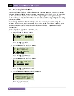
Use the steps below to perform an LTC/Voltage Regulator Test:
a.
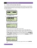
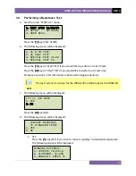
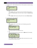
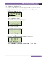
Start from the “START-UP” menu:
Press the
[1]
key (
TEST XFMR
).
b.
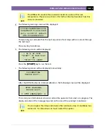
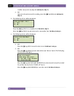
The following screen will be displayed:
Press the
[1]
key (
V1 & V2 TEST
) if you would like to perform a V1 & V2 test.
Press the
[2]
key (
V1 ONLY TEST
) if you would like to perform a V1 test only.
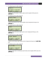
c.
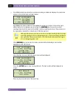
The following screen will be displayed:
Press the
[1]
key (
YES
).
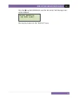
d.
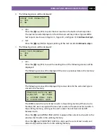
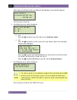
The following screen will be displayed
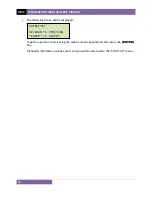
Type the number of taps the LTC or Voltage Regulator has using the alpha-numeric
keypad, and then press the
[ENTER]
key. We will enter “3” for our example.
ENTER # OF RAISE
TAPS, NOT COUNTING
NEUTRAL (1-23):
LTC or VTG REG?
1.
YES
2.
NO
1.
V1 & V2 TEST
2.
V1 ONLY TEST
3.
SPECIAL TEST V1,V2
4.
SPECIAL TEST V1
1.
TEST XFMR 11/02/09
2.
SETUP 12:33:01
3.
USER DIAG

