


REV 2
ATRT-03, ATRT-03A, AND ATRT-03B USER’S MANUAL
84
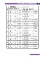
APPENDIX A – TRANSFORMER VECTOR GROUP CODES
Utility power transformers manufactured in accordance with IEC specifications have a Rating
Plate attached in a visible location. This plate contains a list of the transformer's configuration
and operating specifications. One such rating is the winding configuration and phase-
displacement code. This code follows a convention that comprises letter and number sets that
denote three-phase winding configurations (i.e., Wye, delta, or zig-zag). Letter symbols for the
different windings are noted in descending order of their rated voltages. That is, symbols
denoting higher voltage ratings will be in upper-case letters and symbols denoting lower or
intermediate voltage ratings will be in lower-case letters. If the neutral point of either a wye or
zig-zag winding is brought out, the indication will be an N (high voltage) or n (lower voltage).
The end numeral is a 300 multiplier that indicates phase lag between windings.
Accordingly, the following standard practice applies:
Wye (or star) = Y (high voltage) or y (low voltage)
Delta = D (high voltage) or d (low voltage)
Zig-zag = Z (high voltage) or z (low voltage)
For example,
Dyn11
decodes as follows:
D
indicates that the high-voltage windings are connected in a Delta configuration
(Since delta windings do not have a neutral point, the N never appears after a D).
y
indicates that the lower voltage winding is in a wye (or star) configuration.
n
indicates that the lower voltage windings have the neutral point brought out.
11
indicates a phase-displacement lag of 330 degrees between the Wye and the Delta
winding.
Summary of Contents for ATRT-03
Page 14: ...ATRT 03 ATRT 03A AND ATRT 03B USER S MANUAL REV 2 9 Figure 2 ATRT 03A Controls and Indicators...
Page 16: ...ATRT 03 ATRT 03A AND ATRT 03B USER S MANUAL REV 2 11 Figure 3 ATRT 03B Controls and Indicators...
Page 79: ...REV 2 ATRT 03 ATRT 03A AND ATRT 03B USER S MANUAL 74 Figure 22 Test Plan Test Results Printout...
Page 85: ...REV 2 ATRT 03 ATRT 03A AND ATRT 03B USER S MANUAL 80 Figure 23 Sample Test Plan Printout...
Page 91: ...REV 2 ATRT 03 ATRT 03A AND ATRT 03B USER S MANUAL 86...
Page 92: ...ATRT 03 ATRT 03A AND ATRT 03B USER S MANUAL REV 2 87...
Page 93: ...REV 2 ATRT 03 ATRT 03A AND ATRT 03B USER S MANUAL 88...
Page 94: ...ATRT 03 ATRT 03A AND ATRT 03B USER S MANUAL REV 2 89...
Page 95: ...REV 2 ATRT 03 ATRT 03A AND ATRT 03B USER S MANUAL 90...
Page 96: ...ATRT 03 ATRT 03A AND ATRT 03B USER S MANUAL REV 2 91...
Page 97: ...REV 2 ATRT 03 ATRT 03A AND ATRT 03B USER S MANUAL 92...
Page 99: ...REV 2 ATRT 03 ATRT 03A AND ATRT 03B USER S MANUAL 94...
Page 100: ...ATRT 03 ATRT 03A AND ATRT 03B USER S MANUAL REV 2 95...
Page 101: ...REV 2 ATRT 03 ATRT 03A AND ATRT 03B USER S MANUAL 96...
Page 102: ...ATRT 03 ATRT 03A AND ATRT 03B USER S MANUAL REV 2 97...
Page 103: ...REV 2 ATRT 03 ATRT 03A AND ATRT 03B USER S MANUAL 98...
Page 104: ...ATRT 03 ATRT 03A AND ATRT 03B USER S MANUAL REV 2 99...
Page 106: ...ATRT 03 ATRT 03A AND ATRT 03B USER S MANUAL REV 2 101...
Page 107: ...REV 2 ATRT 03 ATRT 03A AND ATRT 03B USER S MANUAL 102...
Page 108: ...ATRT 03 ATRT 03A AND ATRT 03B USER S MANUAL REV 2 103...
Page 109: ...REV 2 ATRT 03 ATRT 03A AND ATRT 03B USER S MANUAL 104...
Page 110: ...ATRT 03 ATRT 03A AND ATRT 03B USER S MANUAL REV 2 105...
Page 111: ...REV 2 ATRT 03 ATRT 03A AND ATRT 03B USER S MANUAL 106...


