


3
1. D
EFROSTING
M
ODE
. . . . . . . . . . . . . . . . . . . . . . . . . . . . . . . . . . . . . . . . . . . . . . . . . . . . . . . . . . . . . . . . . 3
2. C
ONTROLS
. . . . . . . . . . . . . . . . . . . . . . . . . . . . . . . . . . . . . . . . . . . . . . . . . . . . . . . . . . . . . . . . . . . . . 4-15
2.1
I
NTEGRATED
C
ONTROL
. . . . . . . . . . . . . . . . . . . . . . . . . . . . . . . . . . . . . . . . . . . . . . . . . . . . . . . . . . . . . . . . . 4-5
2.2
P
LATINUM
M
AIN
C
ONTROL
. . . . . . . . . . . . . . . . . . . . . . . . . . . . . . . . . . . . . . . . . . . . . . . . . . . . . . . . . . . . 5-9
2.3
D
ECO
-T
OUCH
M
AIN
C
ONTROL
. . . . . . . . . . . . . . . . . . . . . . . . . . . . . . . . . . . . . . . . . . . . . . . . . . . . . . . 10-12
2.4
L
IGHT
-T
OUCH
B
RONZE
M
AIN
C
ONTROL
. . . . . . . . . . . . . . . . . . . . . . . . . . . . . . . . . . . . . . . . . . . . . . . . . 12
2.5
S
IMPLE
-T
OUCH
B
RONZE
M
AIN
C
ONTROL
. . . . . . . . . . . . . . . . . . . . . . . . . . . . . . . . . . . . . . . . . . . . . . . 13
2.6
B
RONZE
M
AIN
C
ONTROL
. . . . . . . . . . . . . . . . . . . . . . . . . . . . . . . . . . . . . . . . . . . . . . . . . . . . . . . . . . . . . . . 13
2.7
O
PTIONAL
A
UXILIARY
C
ONTROLS
. . . . . . . . . . . . . . . . . . . . . . . . . . . . . . . . . . . . . . . . . . . . . . . . . . . 14-15
2.7.1 20/40/60-
MINUTE
P
USH
-B
UTTON
T
IMER
. . . . . . . . . . . . . . . . . . . . . . . . . . . . . . . . . . . . . . . . . . . . . . . . . . . . 14
2.7.2 20-
MINUTE
L
IGHTED
P
USH
B
UTTON
. . . . . . . . . . . . . . . . . . . . . . . . . . . . . . . . . . . . . . . . . . . . . . . . . . . . . . . . . 14
2.7.3 D
EHUMIDISTAT
. . . . . . . . . . . . . . . . . . . . . . . . . . . . . . . . . . . . . . . . . . . . . . . . . . . . . . . . . . . . . . . . . . . . . . . . . . . . . . 15
2.7.4 60-
MINUTE
C
RANK
T
IMER
. . . . . . . . . . . . . . . . . . . . . . . . . . . . . . . . . . . . . . . . . . . . . . . . . . . . . . . . . . . . . . . . . . . 15
3. M
AINTENANCE
. . . . . . . . . . . . . . . . . . . . . . . . . . . . . . . . . . . . . . . . . . . . . . . . . . . . . . . . . . . . . . . . 16-17
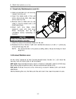
3.1
Q
UARTERLY
M
AINTENANCE
. . . . . . . . . . . . . . . . . . . . . . . . . . . . . . . . . . . . . . . . . . . . . . . . . . . . . . . . . . 16-17
3.2
A
NNUAL
MAINTENANCE
. . . . . . . . . . . . . . . . . . . . . . . . . . . . . . . . . . . . . . . . . . . . . . . . . . . . . . . . . . . . . . . . . . 17
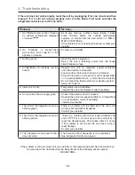
4. T
ROUBLESHOOTING
. . . . . . . . . . . . . . . . . . . . . . . . . . . . . . . . . . . . . . . . . . . . . . . . . . . . . . . . . . . . . . . 18
Table of Contents
1. Defrosting Mode
When the temperature outdoors is below -5°C (23°F), recovery of heat or energy creates
frost in the core.
To maintain its proper operation, the unit is programmed to defrost the recovery core.
The defrost frequency varies according to the temperature ourtoors.
During the defrost cycle, the unit shifts to maximum speed and the dampers close. After
defrosting, the unit returns to the operating mode selected by the user.
R
EPLACEMENT
PARTS
AND
REPAIR
In order to ensure your ventilation unit remains in good working condition, you
must use vänEE genuine replacement parts only. vänEE genuine replacement
parts are specially designed for each unit and are manufactured to comply
with all the applicable certification standards and maintain a high standard of safety.
Any third party replacement part used may cause serious damage and drastically
reduce the performance level of your unit, which will result in premature failing.
vänEE also recommends to contact a vänEE certified service depot for all replacement
parts and repairs.


