background image

www.vanco1.com

800.626.6445

7

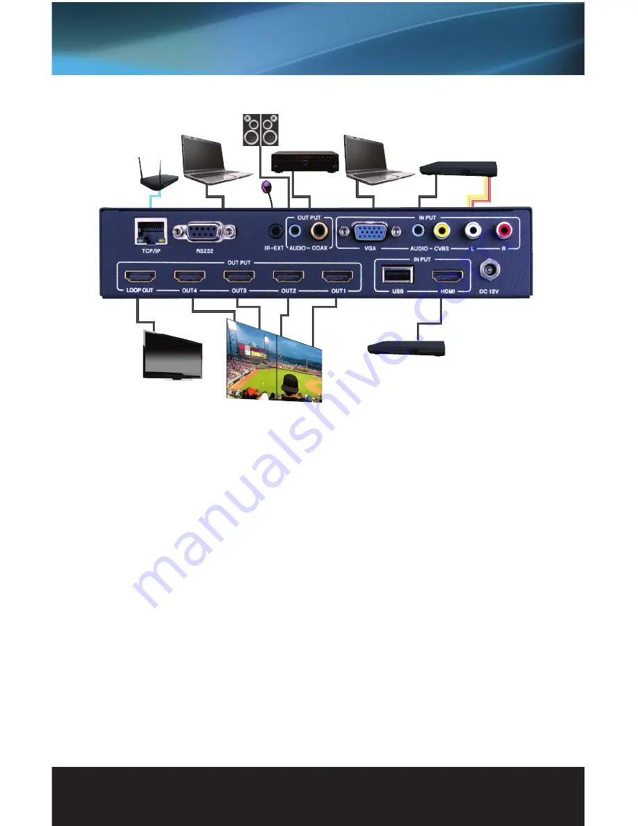
CONNECTION DIAGRAM

CONNECT AND OPERATE

1.  Connect a source such as a PC, Blu-Ray Player, game console, A/V Receiver, Cable or Satellite Receiver, 

etc. to any of the analog or digital inputs on the unit.  Inputs include analog VGA or composite, and digital 
USB or HDMI

2.  Connect displays such as an HDTV or HD Projector to the HDMI output(s) of the unit
3.  Connect an additional EVSP14VW to the “LOOP OUT” port to add more displays for a larger video wall 

setup (OPTIONAL)

4.  For power, connect the provided power supply  

Router

Computer

Computer

DVD/Blu-Ray Player

DVD/Blu-Ray Player

IR TX

HDTV

Video Wall

2.0 Audio 

Stereo Amplifier

At this point the display connected should display the source signal connected to the unit. If no signal is being 
displayed, check all HDMI cables connected. If a display is having difficulty receiving a signal, access the 
display’s menu and adjust the resolution (lowest to highest until signal is displayed). A 24 Hz vertical refresh 
rate may work better than 60 Hz or higher.

IR EXTENSION

The EVSP14VW can be controlled via IR with the included IR remote control. The front panel of the processor 
has an IR sensor that can be pointed to, or as an option, can be hidden and be controlled by the included IR 
Receiver (RX). 
Simply connect the IR Receiver (RX) into the “IR-EXT” port on the back of the unit. The IR Receiver (RX) pigtail 
can be led out to an area where the IR remote control can still reach it line of sight while the main unit is 
hidden. 

Summary of Contents for EVSP14VW

Page 1: ...Vanco Part Number EVSP14VW 1X4 Multi format Video Wall Processor with HDMI Loop out www vanco1 com 800 626 6445 1x4MULTI FORMA T VIDEO WALL PROCESSOR with HDMI Loop out...

Page 2: ...ularly at the plugs 9 Use unit only with accessories specified by the manufacturer 10 Refer all servicing to qualified personnel CAUTION HDMI is a very complex technology requiring continuous authenti...

Page 3: ...t via the built in media player There is no need for a computer or source to display digital signage Control of the unit can be done via IR remote included TCP IP and RS 232 For any video wall applica...

Page 4: ...dio Formats supports PCM audio HDMI supports LPCM Dolby and DTS audio formats ESD Protection Human body model 8kV air gap discharge 4kV contact discharge v Power supply 12V 2 5A DC US EU standards CE...

Page 5: ...router or switch RS232 Connect the included RS 232 cable to a PC IR EXT Connect the included IR Receiver RX for IR control 5 HDMI OUTPUT PORTS 1 4 W LOOP OUT Connect a HDMI displays such as an HDTV o...

Page 6: ...buttons are for Media Player control using the USB input 5 AUDIO OUTPUT VOLUME ADJUSTMENT Adjusts volume for HDMI Digital Coaxial COAX and analog audio output 6 VIDEO WALL FORMAT ADJUSTMENT Adjusts th...

Page 7: ...this point the display connected should display the source signal connected to the unit If no signal is being displayed check all HDMI cables connected If a display is having difficulty receiving a s...

Page 8: ...www vanco1 com 8 ADDITIONAL VIDEO WALL CONFIGURATIONS 2x1 3x1 4x1 2x2 The EVSP14VW out of the box can handle up to 4 displays in multiple video wall configurations including the following...

Page 9: ...800 626 6445 9 ADDITIONAL VIDEO WALL CONFIGURATIONS 1x2 H 1x3 H 1x4 H 1x2 V 1x3 V 1x4 V...

Page 10: ...DMI_253 Evolution 1x4 Multi Format Video Wall Processor with HDMI Loop out_1558 Setting the unit up with an IP Address for conrol 1 Select RS232 COM or TCP mode 2 Select the proper COM of the PC or co...

Page 11: ...of the video signal across the video wall configuration this will adjust for bezel size of the displays Mode Page Setting the Video Wall configuration Simply click on the video wall configuration desi...

Page 12: ...ource input 2 Select the output resolution desired 3 Select the output mode HDMI or DVI 4 Adjust volume or mute SOFTWARE AND USER INTERFACE CONTROL VIA RS 232 Selecting the input source adjusting the...

Page 13: ...begin firmware upgrade process Any updates errors or unsuccessful notifications will display under the Messages section 2 The built in Scaler can also be upgraded with available firmware Download the...

Page 14: ...rder and results in a signal being plugged into a device that is on and will attempt to connect the signal 5 Most of the major source and display manufacturers employ a proprietary control channel to...

Page 15: ...cal Support by dialing 1 800 626 6445 You can also email technical support issues to techsupport vanco1 com When calling please have the Model Number Serial Number affixed to the bottom of the unit an...

Page 16: ...Vanco International 506 Kingsland Drive Batavia Illinois 60510 call 800 626 6445 fax 630 879 9189 visit www vanco1 com...

Reviews: