www.vanco1.com
800.626.6445
5
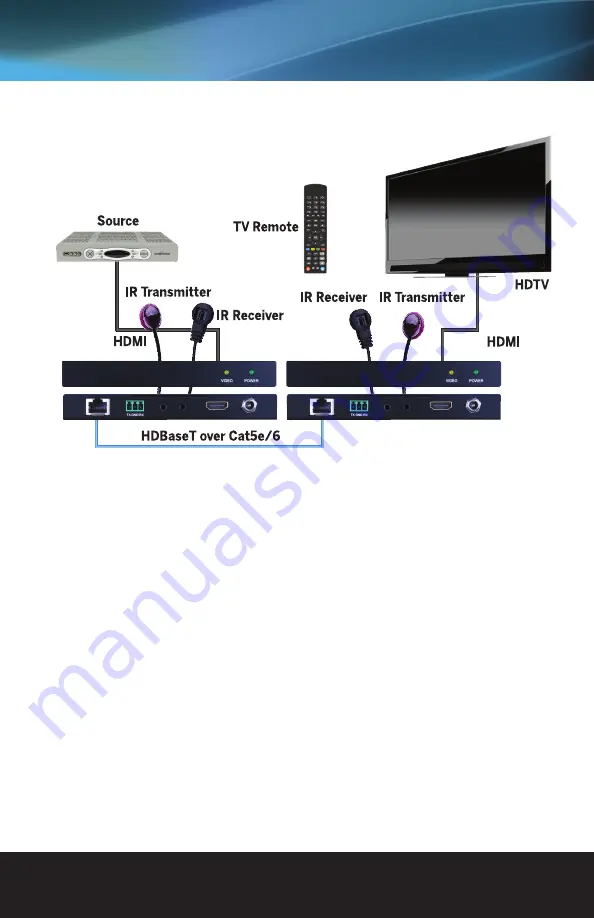
CONNECTION DIAGRAM
1. Connect a source such as a Blu-Ray Player, game console, A/V Receiver, Cable or Satellite Receiver, etc.
to the HDMI input on the Transmitting unit.
2. Connect a display such as an HDTV or HD Projector to the HDMI output on the Receiving unit.
3. Connect a single Category 5e/6/7 (up to 330ft/100m for 1080p or 230ft/70m for 4K) to the UTP output
of the Transmitting unit, and the other end to the UTP input of the Receiving unit.
4. OPTIONAL: When using the bi-directional IR control, connect the IR emitter at either end to the IR OUT
port on either the transmitter or the receiver. When using a powered IR receiver, connect via a 3.5 mm
stereo plug to the IR IN on either the receiver or the transmitter.
5. OPTIONAL: When using bidirectional RS232 control, use the provided 3-conductor screw down terminals
in the proper configuration of the devices being connected. If you are unsure of the TX, RX, and Ground pin
configuration, please contact the manufacturer of the third party device for additional information.
6. For power, plug in either the Transmitting unit or Receiving unit with the included power supply, opposite
unit will not have to be plugged in as it features Power over Ethernet (PoE).
7. Power on each device in the same sequence (receiver and transmitter will already be powered when either
unit is plugged in).
At this point the display connected should display the source signal connected to the extender set. If no signal
is being displayed, connect a shorter Cat5e/6 cable (jumper or patch cable). If a display is having difficulty
receiving a signal, access the display’s menu and adjust the resolution (lowest to highest until signal is
displayed). Use the source remote at the receiver emitter to test IR functionality. If the IR remote function is
not responding, check the emitters to ensure they are placed correctly and are plugged into the correct IR
jacks on the Extender set receiving and transmitting units.


