background image

MS-350 NP Operating Instructions Ver 3.01E

27

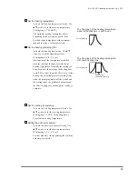
Essential tools:  A Philips screwdriver
Replace when:  The problems listed on "13 Common 

problems and solutions" occurs.

The microswitch is sold individually.

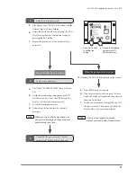
1


Loosen the screws that holds the frame cover in 
place and remove the cover.

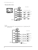
2


Next, loosen the knurled nut that fix the control 
unit base, and push the control unit over to the 
other side. (Refer to “10-8 Replacing the control 
unit” for the detail.) Now you can see the 
microswitch. 

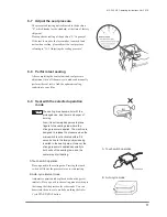
Next, loosen the screws which hold the 
microswitch and remove the terminal that fix 
the wiring.

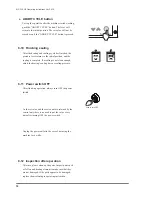
4


When installing a new microswitch, push down 
the pressure lever with your hand. Fix the 
microswith to the position where the 
microswitch is activated with the clicking sound 
when the pressure lever is pushed down with 
the hand.

10-9  Replacing the microswitch

Pressure lever

Microswitch

Warning

 Activating the microswitch by pushing it 

with fingers etc. will be extremely 
dangerous. The improper wiring will cause 
the damage to the control unit.

Warning

 Improper wiring will damage the control 

unit. Connect the wiring properly referring 
to “12 Electric Diagram.”

Warning

 Always unplug the power cord from the 

outlet when replacing the microswitch. 

Summary of Contents for MS-350 NP Series

Page 1: ...MICROCOMPUTER CONTROLLED SEALER FOR STERILIZABLE BAGS MEDICAL POUCH SEALER Printed JAN 2014 3rd Edition 3 01E F TYPE MS 350 NP Series Operating Instructions...

Page 2: ...MS 350 NP Operating Instructions Ver 3 01E 2...

Page 3: ...ur actual machine For operating problems or product information please contact your local dealer or Fuji Impulse Fuji Impulse Co Ltd 4 23 18 Shonai Sakaemachi Toyonaka Osaka 561 0834 Japan Tel 81 0 6...

Page 4: ...ower switch OFF 18 8 12 Inspection after operation 18 9 Safety devices and error messages 19 10 Replacing the routine maintenance parts 20 10 1 Preparation 21 10 2 After the replacement 21 10 3 Replac...

Page 5: ...e that all of the accessories described below are included If not please contact your dealer Code Model Voltage V Power W Sealing Width mm Sealing Length mm Weight kg Machine Dimension mm W x D x H MS...

Page 6: ...withstand high heat 2 Film thickness limits for the MS 350 NP series are described below The machine cannot seal bags which are thicker than that indicated The machine may malfunction if you try to e...

Page 7: ...ated below Please check them before beginning operation Labels not readily apparent are indicated by dotted lines 5 Warning caution label location and content When removing the control unit you will s...

Page 8: ...ectric power plug fully into the wall outlet Warning Do not use for packaging liquids Do not splash water on the machine or use machine for packaging liquids since machine is not waterproof There is a...

Page 9: ...ou place your fingers in this area there is a possibility of burns Do not place hands between the seal jaws pressure lever and seal frame Should the foreign objects such as fingers are clamped between...

Page 10: ...ively high heating temperatures will damage the Teflon glass tape and other consumables as well as result in heating element breakage This will lead to decreased work productivity and unnecessary powe...

Page 11: ...ement will not become hot just by plugging the unit in or turning the power switch to the ON position The heater will only become hot for an instant when the heating process is in operation However af...

Page 12: ...Control unit Digital Display Mode indicator lights Numerical setting arrows Auto cycle START STOP ABORT CYCLE All operations are stopped and the sealer returns to the initial position 1 Set the seal...

Page 13: ...c screw 3 Tighten the screws firmly at the height suitable for your product Install the machine on a flat secure working place Use only as described in this manual There is a risk of danger and malfun...

Page 14: ...ow to set each operation mode The heating temperature heating time heating temperature retaining time cooling temperature and auto cycle interval are set with the control unit The setting values will...

Page 15: ...re controlled machine indicates the time to retain the set heating temperature Normally the sealing can be performed without setting the heating time with 0 0 seconds It will be effective to set the h...

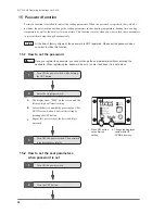
Page 16: ...O CYCL DISPLAY SET FIRST TIME PUSH SET SECOND TIME PUSH SET THIRD TIME PUSH SET FOURTH TIME PUSH set PUSHING FIVE TIMES WILL RETURN YOU TO THE COUNTER MODE TO RESET THE VALUES Power ON MODE DIGITAL DI...

Page 17: ...cycle interval mode Automatic operation takes place based on the preset intervals Place a pouch to the sealing area according to the timing that the pressure lever descends You can deactivate the auto...

Page 18: ...ooling time or sealing pressure After finishing operation always turn OFF the power switch As the set value and the seal count are retained by the control unit there is no need to put the value every...

Page 19: ...e sealing area When heating continues over the heating retaining time When the heating continues over 3 seconds after the heating starts the power switch automatically turns OFF to shut down the heati...

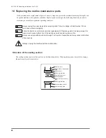
Page 20: ...ture of the sealing section W15mm Semi Transparent Tape Pressure lever Silicone rubber white W38mm glass tape W40mm Teflon center dry tape Sarcon sheet Heating element Temperature sensor W38mm glass t...

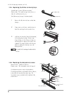
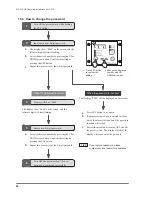
Page 21: ...e cover 2 Loosen the pressure adjusting nut fastening screw do not completely remove it and turn the pressure adjusting nut counterclockwise to remove it Now you can remove the small lever pressure ru...

Page 22: ...f the clamping lever Apply the tape so that the non adhesive central part of the tape covers the heating element Essential tools A Philips screwdriver Replace when The temperature sensor is damaged Th...

Page 23: ...so that there is no slacking between the temperature sensor fixing plate the A 1 side and the temperature sensor fixing plate the A 2 side 7 Fix the temperature sensor module 8 Install the heating el...

Page 24: ...3 so the heating element is stretched tight When the screw B is not tightened enough the heating element will not be stretched tight enough which may result in damaging the heating element 7 Fix the t...

Page 25: ...ss tape at 365mm of length and adhere it over the Sarcon sheet 1 pc 5 Fold the glass tape along both edges so that the excess tape over the clamping lever adheres to the sides of the pressure lever 6...

Page 26: ...included in the maintenance parts kit 1 Remove the 38mm width glass tape adhered on the silicone rubber 2 Using an industrial purpose alcohol etc completely remove the adhesive residues remaining on...

Page 27: ...hold the microswitch and remove the terminal that fix the wiring 4 When installing a new microswitch push down the pressure lever with your hand Fix the microswith to the position where the microswitc...

Page 28: ...ered position due to the solenoid suction strength dropping and the microswitch not being activated 3 The pressure adjusting nut will stop roughly at the position of H as in the right illustration 4 T...

Page 29: ...n be slid back and forth to adjust the depth of the pouch insertion Adjust the seal gauge position so the heating element comes to the place you would like to seal Once the seal position is determined...

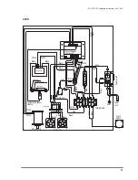
Page 30: ...Black Gray Gray Touch switch Black Black White Microswitch Red Red Black Black Black Black Black White White Gray Gray Gray Black Yellow TRIAC Transformer Electrode Heating element Temperature sensor...

Page 31: ...ol unit Power switch Yellow Earth Grey Black Black Temperature sensor module Red Transformer Blue White White White White White Terminal strip DC solenoid 1 2 3 4 5 6 7 8 9 10 11 12 Cooling fan Yellow...

Page 32: ...the power plug fully plugged in Insert the power plug fully into the outlet Is the power plug damaged Replace the power cord or power plug Is the fuse on the back of the control unit blown Replace the...

Page 33: ...n glass tape Sarcon sheet and silicone rubber white damaged Replace the Teflon glass tape Sarcon sheet and silicone rubber white Is the pressure adjusting nut is set in the proper position Adjust the...

Page 34: ...re you using the heating element specified by Fuji Impulse Turn OFF the power switch Do not use the extension cord Use only the specified heating element Is the temperature sensor shifted or displaced...

Page 35: ...MS 350 NP Operating Instructions Ver 3 01E 35...

Page 36: ...e interval time This function is useful when you want to lock these parameters to prevent them being changed unexpectedly a The display show 0000 on the screen and the leftmost digit will start flashi...

Page 37: ...display will show the display where you enter the password a The HEAT TEMP SETTING lamp will turn ON b Set the desired heating temperature with UP DOWN arrow key Press the SET button The display will...

Page 38: ...ess SET button to try again b If an incorrect password is entered for three times the alarm will sound and the password function will locked c Restart the machine by turning OFF and ON the power switc...

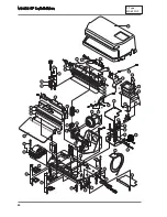
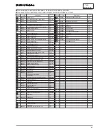
Page 39: ...tructions Ver 2 10E 39 When ordering spare parts please consult the exploded view diagram spare parts list on the following pages and provide both the part name and code number to your local dealer Ex...

Page 40: ...32 51 26 28 49 25 27 69 68 67 66 45 33 48 46 70 65 18 54 44 57 43 42 41 41 59 55 56 55 56 37 40 62 17 13 12 21 1 22 20 2 30 29 23 21 2 24 5 7 8 a b A 14 16 15 19 34 71 a 25 b 9 MS 350 NP Exploded Vie...

Page 41: ...0 Planger stopper sponge 2pcs set 28 492800 Shock absorber with nut 1 pc 29 421700B H type electrode 2pcs set 30 421702B Terminal cover 2pcs set 32 493201 Frame cover 1 pc 33 493300 Microswitch 1 pc 3...

Page 42: ...http www fujiimpulse co jp Y6602 JAN 2014 3rd Edition MS 350 NP Operating Instruction 3 01E...

Reviews: