background image


VAL

S

TEAM


ADCA


Produced in accordance with Sound Engineering Practices of the European PED - Pressure Equipment Directive.   


 IMI P130.08 E 00.20

15

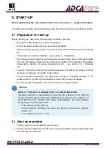
5. START-UP

Before performing the start-up procedure, refer to section 1 – Safety information.

The start-up procedure must be followed every time the product is put back into service. 

5.1. Preparation for start-up 

Before starting up, make sure the following conditions are met:

•  All works on the system have been completed. 
•  All the necessary safety devices have been installed. 
•  When required, warning notices are used to alert others that the system is starting 

up.

•  The product is correctly installed – see section 4 – Installation. 
•  Referring to these Installation and Maintenance Instructions (IMI), Information Sheet 

(IS) and nameplate, check that the product is suitable for the intended installation: 

temperature, medium, pressure, temperature, etc. – see section 1.2 – Intended 

use. 

• 

A safety check was performed by qualified personnel. Checking for leaks, structural 

damage and integrity of system components.

•  For spring-loaded regulators, the adjustment spring is completely relaxed. If not, 

release tension by turning the adjustment knob (26) counterclockwise. 

•  For dome-loaded regulators, the dome chamber is depressurized.  

RISK OF PRODUCT DAMAGE DUE TO CONTAMINATION

The plant operator is responsible for cleaning the pipelines in the plant as 

well as keeping the product well maintained. At start-up,


the presence of 

small particles in the medium (dirt, scale, weld splatters, etc.) may damage 

the product or cause malfunction.  

•  Flush pipelines before start-up.
• 

Clean  protection  varnishes  from  pipes  and  flanges,  leftover  paint,  graphite, 

grease, etc. 

• 

Use a pipeline strainer or a filter. 

NOTICE

5.2. Start-up procedure

1. 

Partially open the downstream shut-off valve. 

2. 

Slowly open the upstream shut-off valve to prevent sudden surges of pressure that 

can damage the regulator.  

Summary of Contents for PURE P130

Page 1: ...ign and material of this product without notice Produced in accordance with Sound Engineering Practices of the European PED Pressure Equipment Directive IMI P130 08 E 00 20 P130 INSTALLATION AND MAINT...

Page 2: ...s accessible to every user and make these instructions available to every new owner of the product Current regional and plant safety regulations must be considered and followed during installation ope...

Page 3: ...Certification 9 2 3 Product identification 10 2 4 Technical data 10 2 5 Factory assembly and cleaning 10 3 TRANSPORT STORAGE AND PACKAGING 11 4 INSTALLATION 12 4 1 Preparation for installation 13 4 2...

Page 4: ...inor injury CAUTION Situation which if not avoided can result in property damage or product malfunction NOTICE Indicates additional information tips and recommendations NOTE 1 2 Intended use Refer to...

Page 5: ...to these Installation and Maintenance Instructions Where a formal Permits to Work system is implemented in the plant it must be complied with 1 4 Personal protective equipment Personal protective equi...

Page 6: ...nstalled Check the product Information Sheet IS Install a safety device Before starting any work on the product depressurize it and cool or heat it up to ambient temperature This also applies to the l...

Page 7: ...SULT OF ILLEGIBLE INFORMATION Important information written in the product nameplate markings and warning signs may wear overtime or get illegible due to e g dirt accumulation resulting in hazardous s...

Page 8: ...ressure reducing valves are designed for use with clean air nitrogen carbon dioxide oxygen argon and other gases or liquids compatible with the construction materials and valve design These valves are...

Page 9: ...set pressure as long as the downstream system is demanding flow Since the P130J P130H and P130G are balanced plug regulators downstream pressure flows through an orifice on the plug to the balancing c...

Page 10: ...efer to IS PV20 00 Technical Information Sheet ADCAPure for further information 2 3 Product identification The following items are indicated on the product nameplate or directly on its body Manufactur...

Page 11: ...AGE DUE TO IMPROPER STORAGE Do not remove any packaging or protective covers until immediately before installation at the site Store the product in a solid base in a dry cool and dust free environment...

Page 12: ...the product is safely held in place during installation Wear protective safety shoes WARNING RISK OF INJURY AND PRODUCT MALFUNCTION DUE TO PRESSURIZED SPRING CHAMBER Plugging or isolating the captured...

Page 13: ...to this Installation and Maintenance Instructions IMI Information Sheet IS and nameplate check that the product is suitable for the intended installation temperature medium pressure temperature etc se...

Page 14: ...ng as well as protective covers which are placed on clamps or ETO connections Make sure the regulator is free from foreign matter 2 Handle the regulator carefully to prevent damage to its surface fini...

Page 15: ...e medium pressure temperature etc see section 1 2 Intended use A safety check was performed by qualified personnel Checking for leaks structural damage and integrity of system components For spring lo...

Page 16: ...pressurized This will allow pressure to build up slowly 6 Operate the regulator until the desired set pressure is achieved In spring loaded regulators make sure the final adjustment is made in the dir...

Page 17: ...ve to stop the process medium from flowing through the pressure regulator 3 Allow medium to cool down and completely drain it from the pipeline and pressure regulator 4 Make sure the pipeline and pres...

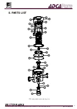
Page 18: ...with Sound Engineering Practices of the European PED Pressure Equipment Directive IMI P130 08 E 00 20 18 8 PARTS LIST 3 8 9 11 4 6 10 1 5 14 15 16 18 20 19 17 21 25 24 2 27 26 30 22 29 28 23 P130L sp...

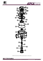
Page 19: ...nd Engineering Practices of the European PED Pressure Equipment Directive IMI P130 08 E 00 20 19 29 28 22 24 25 23 26 27 30 16 14 1 15 18 20 19 10 9 6 5 8 11 4 3 21 2 2A 12 7 17 P130K P130J P130H and...

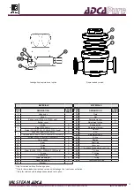
Page 20: ...130H P130G only X 8 Valve spring X 9 Seat X 10 O ring X 11 Guide X 12 Stem P130K P130J P130H P130G only X 13 O ring X 14 Pusher disk 15 Lower diaphragm X 16 Upper diaphragm X 17 Washer MATERIALS POS N...

Page 21: ...ent spring 21 or disconnect loading control pressure supply If the valve is removed from the line fix the valve body 1 in a vise with soft jaws with the bottom cover 3 pointing upwards 2 Unscrew the b...

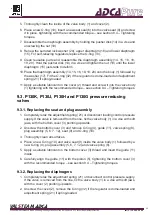
Page 22: ...ody 1 tightening with the recommended torque see section 9 4 Tightening torques 9 3 P130K P130J P130H and P130G pressure reducing valves 9 3 1 Replacing the seat and plug assembly 1 Completely relax t...

Page 23: ...13 7 Clean reusable parts and reassemble the diaphragm assembly 14 15 16 18 19 20 Hold the pusher disk 14 in a vise and tighten the nut 19 until the lower diaphragm 15 just starts to deform 8 Place t...

Page 24: ...he valve or flow restriction is limiting flow through the valve Remove foreign matter and consider installing a filter upstream of the regulator Check and solve flow restrictions e g fully opening a p...

Page 25: ...inating fluids and residues or mechanical damage that may represent a health safety or environmental risk must be provided in writing when returning products to VALSTEAM ADCA RISK DUE TO PRESENCE OF H...

Reviews: