Valor President ZC Cast Front 536CXB Installation Manual Download Page 6

6

Installation

1.  Fit the top baffle under the top panel of the appliance 

case. Secure with 2 thread forming screws.

2.  Fit the stand-off spacers. The stand-off spacers for 

these installations are supplied flat. They are left and 

right handed.

3.  Remove the 2 screws near each of the rear top 

corners of the appliance and the 2 screws near each 

side of the top back corners.

4.  Bend the spacers as shown.
5.  Screw the spacers to the rear of the appliance using 

the screws just removed.

6.  Bend the side wings of the spacers to align the 2 

holes in each spacer with those in the appliance sides. 

Secure the spacers using the screws just removed.

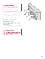
7.  Mount the framing 

plate to the 

appliance.

8.  Secure the framing 

plate and brackets 

to the sides of the 

appliance case with 

4 thread cutting 

screws supplied. 

Screw from the 

outside through the 

access holes in the 

framing plate.

Note: There are 

alternate methods of 

finishing around the 

framing plate—either 

leaving it exposed 

or recessing it and 

covering it up with 

the wall finish. See 

page 4.

9.  Install the plinth and the rear base support below 

the firebox (optional). 

The purpose of the plinth is to allow the appliance 

to be placed on a rough subfloor, such as plywood, 

without regard for the additional thickness of floor 

finishes as the appliance bottom must otherwise 

be placed at the finished hearth height or the front 

trims will not fit properly on the appliance.
a)  Detach the burner module from the appliance 

by removing its 11 screws.

WARNING

Failure to install the stand-off spacers 

Failure to install the stand-off spacers 

may result in a fire hazard and void the 

may result in a fire hazard and void the 

warranty.

warranty.

Summary of Contents for President ZC Cast Front 536CXB

Page 1: ...this appliance and must be installed for the protection of children and other at risk individuals INSTALLER Leave this manual with the appliance CONSUMER Retain this manual for future reference INSTA...

Page 2: ...e heater up so the bottom of the heater sits at the finished floor hearth height otherwise the cast front will not sit at the proper height A non combustible hearth is not required in front of this ap...

Page 3: ...Outlet ZC Stand offs 6 5 8 dia 6 5 8 dia 21 5 8 25 1 4 31 5 7 8 plinth insul 2 26 1 4 20 26 11 9 5 D E Mantel leg See table 2 Mantel depth A Min clearance B Up to 7 4 Above 7 up to 8 5 Above 8 up to 9...

Page 4: ...e finish and backing required Tighten screws after wall finish to pull brackets tight Cast Front Framing Plate Cover brackets Cover Framing Plate up to holes Wall Finish note any material covering fra...

Page 5: ...ar Minimum 11 Allow extra for rear vent elbows Top of finished hearth or floor Wall Finish Note Header is raised to accomodate top vent clearances 39 to header includes plinth reduce by 7 8 if not usi...

Page 6: ...the appliance case with 4 thread cutting screws supplied Screw from the outside through the access holes in the framing plate Note There are alternate methods of finishing around the framing plate ei...

Page 7: ...the top insulation layer For top vent outlet appliances cut out a circle at the center of the insulation layer for the vent collar Place the insulation layer on top of the appliance case inboard of th...

Page 8: ...he front unit Unhook the front unit Lift it up by holding the decorative grille DO NOT lift it by holding the top Always securely replace the window the front and the barrier screen before lighting WA...

Page 9: ...Ba e 569019 340B252AZ 1 11 Rear Base Support 569079 340B236 1 12 Plinth 569059 350K967 1 13 Framing Plate 4000469 4000469 1 14 Heater Mounting Bracket 4000489 4000489 2 15 ZC Stand o LH 569039 340B235...

Page 10: ...trait Devanture de fonte President 536CXB Homologu pour usage avec les foyers Valor Portrait 530 seulement Incompatible avec les foyers encastrables 530INI IPI INSTALLATEUR Laissez cette notice avec l...

Page 11: ...ale le permettent Exigences pour la base de foyer Une plinthe de d paisseur est incluse avec la devanture Cette plinthe permet de soulever le foyer de fa on ce que la devanture de fonte une fois insta...

Page 12: ...sus carteurs Dia 6 5 8 Dia 6 5 8 21 5 8 25 1 4 31 5 Plinthe de 7 8 isol 2 26 1 4 20 26 11 9 5 D E Patte du manteau voir table 2 Profondeur A du manteau D gagement minimum B Jusqu 7 4 De 7 8 5 De 8 9 7...

Page 13: ...anguettes selon l paisseur de OD QLWLRQ GX PXU pouces mm pouces mm D tail des languettes Devanture de fonte couvre les supports 0DW ULDX incombustibles seulement au dessus de la plaque d encadrement 7...

Page 14: ...plancher fini ou de la base de foyer Finition du mur Note La poutre de t te est plus haute pour accomoder les d gagements pour l vacuation par dessus 39 la poutre de t te plinthe incluse r duisez de 7...

Page 15: ...il 8 Fixez la aux c t s de la bo te de foyer avec 4 vis auto taraudeuses fournies Vissez la plaque de l ext rieur travers les fentes de ses c t s Note Il y a 2 m thodes de finition autour de la plaque...

Page 16: ...n cercle au centre de l isolant pour faciliter le passage du conduit d vacuation Placez l isolant sur le dessus de la bo te de foyer l int rieur des carteurs 5 Si n cessaire vissez les crochets l arri...

Page 17: ...ase d ammoniaque Enl vement de la devanture D crochez la devanture en la tenant sous la parure ornementale du haut NE PAS soulever la devanture par son bord sup rieur Toujours remettre la fen tre et l...

Page 18: ...50K065AZ 1 10 D flecteur d air 569019 340B252AZ 1 11 Support de base arri re 569079 340B236 1 12 Plinthe 569059 350K967 1 13 Plaque d encadrement 4000469 4000469 1 14 Montants pour la plaque 4000489 4...

Reviews: