Valmet Flowrox SKW DN50-600 Installation Maintenance And Operating Instructions Download Page 40

4SK70EN - 5/2023

12

4  Installation

 WARNING!

Crushing and cutting hazard.

Do not put your hands or fingers into the tower or 

port areas when the valve cycles.

Do not energize the actuator before the valve is 

properly attached to the pipeline.

Disconnect and de-energize the actuator before 

installation and maintenance work.
High pressure injection hazard.

Do not use higher pressure than rated for the valve. 

Higher pressures can cause serious damage to the 

valve or harm to operating personnel.

 CAUTION!

Harmful substance hazard.

If the process medium has to be fully contained, is 

corrosive or harmful, make sure the flushing ports 

are piped to a safe location.

Never use the valve with all flushing ports 

plugged. Accumulated solids can cause the valve 

to jam.

4.1  General

Flowrox gate valves are normally delivered fully assembled 

and ready for use. Only personnel with appropriate training 

are allowed to install the valves. If the valve is delivered 

without an actuator or accessories, they must be installed in 

accordance with the manufacturer’s instructions. 

Flowrox gate valves have connections with DIN or ANSI 

bolt drillings as standard design, but other drillings are also 

available, such as BS, AS, JIS.

Reserve enough space for safe installation and maintenance. 

See 

Appendix A

 for valve dimensions. Notice that during 

opening and closing cycles, a small amount of medium is 

discharged in the valve body cavity; therefore do not install 

gate valves above walkways or critical components. Flushing 

and drainage connection must be installed if medium is 

harmful or corrosive. 

If the valve has been stored in the warehouse, lubricate the 

valve as instructed in the 

Lubrication

 chapter.

4.2  Flow direction, support, and valve 

position 

Do not install DN250 or larger valves in other 

than vertical position without support.

Do not step on a valve installed in horizontal or 

angled position.

The valve does not have an intended flow direction; therefore 

it can be installed either way in the pipeline. 

Proper pipe support must be placed on either side of the valve 

to support the weight of the pipe. The valve must never be 

used to support the pipes.

The valve can be installed in any position other than below 

horizontal. Flushing will not work in installations below 

horizontal level and it will lead to leaking and nonfunctional 

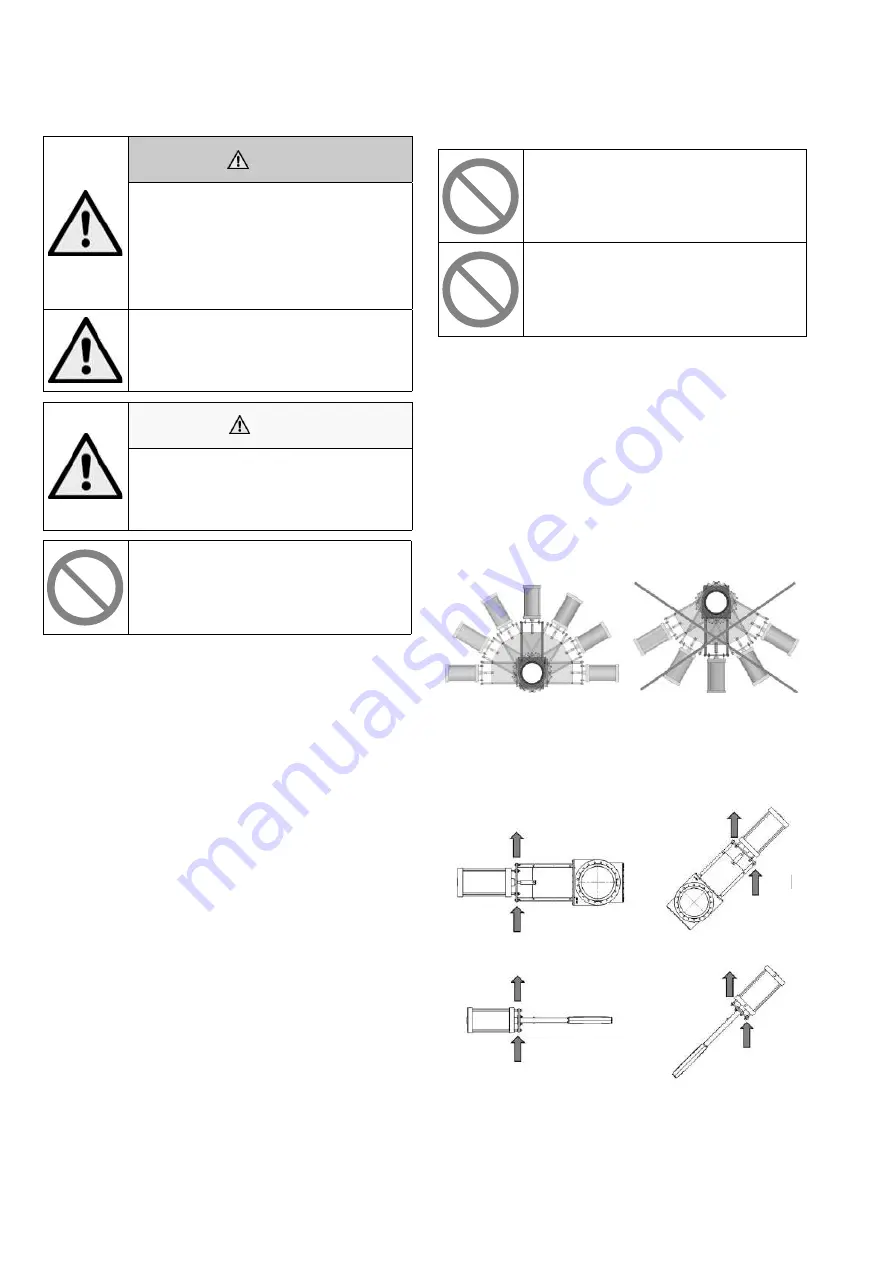
valve. See the following Figure 7.

Recommended installation 

positions

Forbidden installation positions

Figure 7.  Installation alternatives for SKW and SKF 

valves.

Horizontal installation.

Support is required as shown or 

otherwise.

Angled installation.

Support is required as shown or 

otherwise.

Figure 8.  Support for automatically actuated valves.

Summary of Contents for Flowrox SKW DN50-600

Page 1: ...Valmet 4SK70ZHS 6 2022...

Page 2: ...4SK70ZHS 6 2022 2...

Page 3: ...3 4SK70ZHS 6 2022...

Page 4: ...4SK70ZHS 6 2022 4...

Page 5: ...5 4SK70ZHS 6 2022...

Page 6: ...4SK70ZHS 6 2022 6 2 0 to 75 7 2 3 4...

Page 7: ...7 4SK70ZHS 6 2022 H...

Page 8: ...4SK70ZHS 6 2022 8 2 3 4 2 2 5 6 7 8 4 2 2...

Page 9: ...4SK70ZHS 6 2022 2 3 4 2 2 5 6 7 8 4 2 2...

Page 10: ...4SK70ZHS 6 2022...

Page 11: ...4SK70ZHS 6 2022 3...

Page 12: ...4SK70ZHS 6 2022 4...

Page 13: ...4SK70ZHS 6 2022...

Page 14: ...4SK70ZHS 6 2022...

Page 15: ...4SK70ZHS 6 2022 5 6...

Page 16: ...4SK70ZHS 6 2022 4 2 7 cm3 cm3...

Page 17: ...4SK70ZHS 6 2022...

Page 18: ...4SK70ZHS 6 2022...

Page 19: ...4SK70ZHS 6 2022 Nm...

Page 20: ...4SK70ZHS 6 2022 20...

Page 21: ...4SK70ZHS 6 2022...

Page 22: ...4SK70ZHS 6 2022 22 DN D F U K N S V W H H H D F U K N S V W H H H...

Page 23: ...23 4SK70ZHS 6 2022 DN D F U K N S V W H H H D F U K N S V W H H H...

Page 24: ...4SK70ZHS 6 2022 24 SKW 2 0 SKW SKF H 400V 50Hz H 380V 50Hz 440V 50Hz D 525V 50Hz 460V 60Hz N 4 6...

Page 25: ...25 4SK70ZHS 6 2022 2 3 4 5 6 7 8 0 2 4 S2 S3 S4 S5 S6 S7 S8...

Page 26: ...4SK70ZHS 6 2022 26 F F5 H S S5 Z2 Z3 Z5 Z6...

Page 27: ...27 4SK70ZHS 6 2022 Z7...

Page 28: ...Valmet 4SK70ZHS 6 2022...

Page 29: ...ion maintenance and operating instructions Flowrox Slurry Knife Gate valves SKW DN50 600 Wafer SKF DN80 600 Flanged These instructions must be read carefully and understood prior to the installation u...

Page 30: ...NG THEIR FUNCTIONS EVERYONE MUST BECOME FAMILIAR WITH ALL INSTRTUCTIONS IN THIS MANUAL BEFORE ANY INSTALLATION USE MAINTENANCE REPAIR OR ANY OTHER ACTIONS OF THE RESPECTIVE GOODS AND OR SERVICES WHICH...

Page 31: ...alves 6 2 3 Using the valve in explosive conditions 6 2 4 General description 6 2 5 Principle of operation 6 2 6 Mechanical structure 7 2 7 Technical Specifications 10 2 8 Product identification 10 3...

Page 32: ...irective 2006 42 EC Annex IIB partly completed machinery As the product may be used as parts or components in machinery we declare that this product must not be put into service until the relevant mac...

Page 33: ...nderstand the operation and maintenance instructions before using the product Mandatory action symbol Obey these instructions to prevent machine malfunctions Forbidden action symbol Prevent accidents...

Page 34: ...tructure Removable ring sleeves on both sides of the gate provide a bi directional bubble tight seal In the open position the two ring sleeves seal against each other in the centre of the valve provid...

Page 35: ...ves can be delivered with the actuator options shown in Figure 2 Alternative actuators Manual actuator type depends on the valve size Figure 2 Alternative actuators Type Description M Manual actuator...

Page 36: ...9 18 15 6 7 21 22 10 11 12 14 17 1 Figure 3 Exploled view of SKW valve Table 3 SKW valve part list Part Description Part Description 1 Ring sleeve 12 Washer 2 Body SKW 13 Plug 3 Tower 14 Grease nippl...

Page 37: ...2 14 17 NOT AVAILABLE ON ALL OPTIONS SIZES 1 1 Exploled view of SKF valve Table 4 SKF valve part list Part Description Part Description 1 Ring sleeve 12 Washer 2 Body 13 Plug 3 Tower 14 Grease nipple...

Page 38: ...ment to ISO 8573 1 2010 7 4 4 is recommended If any component used on the valve has a stricter requirement pressure air quality the stringent shall prevail Use correct sized pneumatic hoses to ensure...

Page 39: ...n of the cylinders 6 Protect valve ring sleeves from heat light and exposure to ozone 7 Cover the flange openings 8 Do not store any objects on the rubber ring sleeves 9 Follow actuator instructions f...

Page 40: ...afe installation and maintenance See Appendix A for valve dimensions Notice that during opening and closing cycles a small amount of medium is discharged in the valve body cavity therefore do not inst...

Page 41: ...ct automatic actuator to power supply 7 Connect flushing connection if applicable 8 Check that all connections have been fastened and the actuator is installed correctly 9 Run a few open close cycles...

Page 42: ...ot readily available Larger diameter valves can have additional flushing connection to ensure proper flushing Flushing connection are on the sides bottom or on the face of the valve Hole sizes are sho...

Page 43: ...e is operated The flushing water is then left on for the entire cycle and for a minimum of 10 seconds after the cycle To improve flushing the water should be left on until clean flushing water is exha...

Page 44: ...ication Use only silicone based lubricants such as DOW 111 DOW 4 DOW 44 GENERAL ELECTRIC COMPOUND G661 AND RHONE POULENE RHODORSIL III Flowrox gate valves have grease nipples on both sides of the valv...

Page 45: ...nnect automatic actuator to power supply and remove locking pins 13 12 Run a few test strokes before the pipeline is pressurized 6 5 Changing the ring sleeves To change the ring sleeves the valve need...

Page 46: ...linder shaft The position is needed in valve assembly 7 Remove the clevis locking screw 15 and the clevis 14 8 Remove the bolts from between the actuator and tower or adapter plate if equipped Lift th...

Page 47: ...15 It is to prevent excessive gate drop before clevis pin is installed 4 Apply recommended silicon lubricant on the chamfered edge and sides of the gate 2 and slide it through the opening at the top...

Page 48: ...rn 8 Loosen the clevis locking screw 15 9 Rotate the clevis 14 on the stem to adjust it up or down according the dimension measured above 10 Re install the clevis and test if the locking pins 13 fit i...

Page 49: ...en close or valve is not tight Fault in actuator limit switch or control system Check and fix actuator operation Clogged up with solids Clean gate and body cavity Check or install flushing Damaged gat...

Page 50: ...size inch Dimensions in inch Weight in lbs T B B C D E F G J U K N P R S V W M MG A H E MG M A MG E H M MG A E H 3 2 13 2 28 6 50 4 02 22 28 23 07 13 78 4 33 44 37 G1 2 4 2 24 2 40 7 87 4 41 24 72 26...

Page 51: ...E F G J U K N P R S V W M MG A H E MG M A MG E H M MG A E H 3 6 89 7 05 7 87 4 41 24 72 26 89 29 09 3 15 13 78 4 33 20 20 70 68 125 G 1 2 4 6 89 7 05 9 06 5 20 25 51 28 54 29 57 3 94 13 78 4 72 7 87...

Page 52: ...he new type code on valve and actuators see the product Technical bulletin 4 Sign Flange drilling J PN 10 EN 1092 K PN 16 EN 1092 L PN 25 EN 1092 M PN 40 EN 1092 C ANSI 150 ASME B16 5 D ANSI 300 ASME...

Page 53: ...com flowcontrol Subject to change without prior notice Neles Neles Easyflow Jamesbury Stonel Valvcon and Flowrox and certain other trademarks are either registered trademarks or trademarks of Valmet O...

Reviews: