background image

5

4EXP70EN - 9/2023

2  General safety instructions

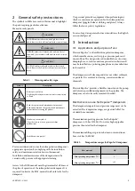
The symbols in Table 1 are used in this manual to highlight 

the parts requiring particular attention.
Hazard severity panels.

 DANGER!

DANGER indicates a hazard with a high level of risk 

which, if not avoided, will result in death or serious injury.

 WARNING!

WARNING indicates a hazard with a medium level of 

risk which, if not avoided, could result in death or serious 

injury.

 CAUTION!

CAUTION indicates a hazard with a low level of risk 

which, if not avoided, could result in minor or moderate 

injury.

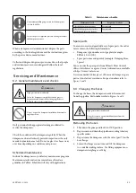
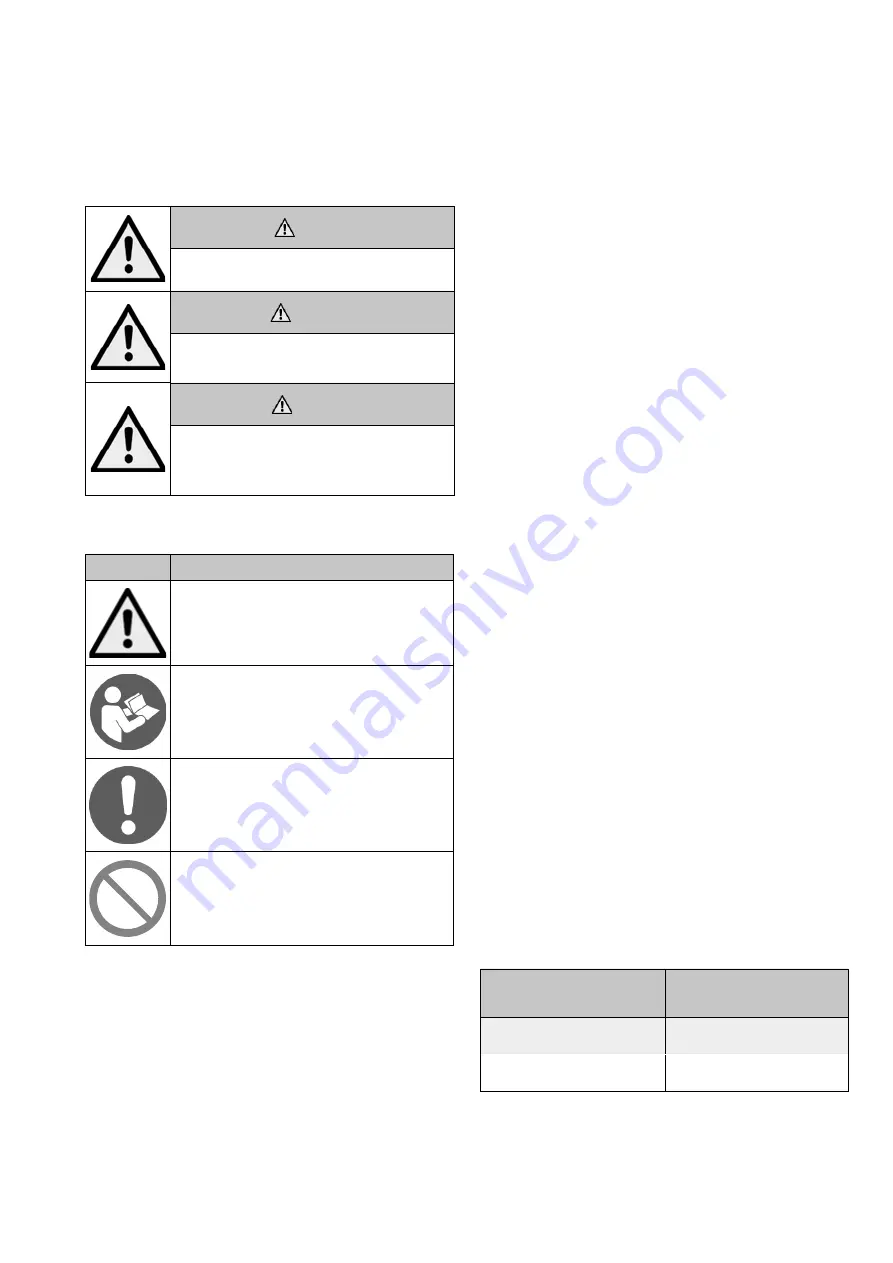
Table 1. 

Warning and safety signs.

Symbol

Description

Risk to personal safety:                                       

Neglecting the safety measures can cause serious injury 

or death.

Read  the  operation  and  maintenance  instructions:                                            

Read and understand the operation and maintenance 

instructions before using the product.

Mandatory action symbol:

Obey these instructions to prevent machine 

malfunctions.

Forbidden action symbol.

Prevent accidents and ensure the inline pulsation dampener’s 

appropriate operation by complying with the installation, 

safety, and maintenance instructions in this manual. 

Installation and maintenance of the dampener must be 

carried out by persons with appropriate training. 

Access to the IOM-manual must be guaranteed at all times at 

the place of operation of the inline pulsation dampener. It is 

required to observe the IOM-manual in all work tasks for the 

dampener.

Use personal protective equipment when performing any 

checks or maintenance operation for the inline pulsation 

dampener (goggles, helmet, clothing and gloves). Always 

follow the factory safety regulations.

In case of any discrepancies between translations, the English 

version shall prevail.

3  Introduction

3.1  Applications and purpose of use

Flowrox Expulse™ is a flexible inline pulsation dampener, 

which smoothes noises, restless pipes, pressure peaks and 

uneven flows. The design is based on double hose structure; 

damping hose, cover hose and compressed air in between. It 

may be installed on a pulsating pump from any manufacturer 

in the market.

The dampener is self-cleaning and does not collect sediment 

or particles. It is resistant to wearing, corrosion and most 

chemicals.

Flowrox Expulse™ provides a flexible connection to the pump 

and tolerates possible misalignments in the pipeline. The 

dampener can also be easily removed if needed.

Restrictions on use for Expulse™ dampeners

The dampener temperature and pressure range must not be 

exceeded. The temperature ranges are given in Table 2 for 

standard hose materials.

The maximum operating pressure for the Expulse™ 

dampeners is 10 bar (1 MPa). Do not use higher pipeline 

pressure than rated for the dampener.

The maximum filling air pressure between outer and inner 
hoses is 6 bar (0,6 MPa)

Table 2. 

Temperature ranges for Expulse™ dampeners.

Hose material

NR

Min operating temperature (

°

C)

0

Max operating temperature (

°

C)

+95

Summary of Contents for Flowrox Expulse Series

Page 1: ...tion and maintenance instructions for Flowrox Expulse Dampener DN32 DN100 These instructions must be read carefully and understood prior to the installation use and servicing of this product Installat...

Page 2: ...NG THEIR FUNCTIONS EVERYONE MUST BECOME FAMILIAR WITH ALL INSTRTUCTIONS IN THIS MANUAL BEFORE ANY INSTALLATION USE MAINTENANCE REPAIR OR ANY OTHER ACTIONS OF THE RESPECTIVE GOODS AND OR SERVICES WHICH...

Page 3: ...over Table of Contents 1 EU DECLARATION OF CONFORMITY 4 2 General safety instructions 5 3 Introduction 5 3 1 Applications and purpose of use 5 3 2 General description 6 3 3 Technical data 8 4 Transpor...

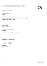
Page 4: ...n dampener size range DN32 DN100 is in conformity with the European Community s Directive PED 2014 68 EU Categorization Category I Properties of fluid PED Article 13 Fluid group 2 Conformity assessmen...

Page 5: ...ired to observe the IOM manual in all work tasks for the dampener Use personal protective equipment when performing any checks or maintenance operation for the inline pulsation dampener goggles helmet...

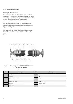
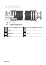
Page 6: ...ampener provides full bore through which the medium can travel The main components are shown in Figure 1 and Figure 2 The dampening effect can be adjusted with the air pressure Normally the needed pre...

Page 7: ...of DN80 and DN100 Flowrox Expulse dampener Part Description Part Description 1 Damping hose 7 Valve 2 Cover hose 8 Plug 3 Pulsation hose connector 9 Lock nut 4 Pulsation hose flange 10 O ring 5 Hose...

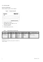
Page 8: ...etc 4 Nominal diameter pressure class Table 3 Expulse dampener model key table Type Size DN Pressure class PN Flanges Con nector Flange Connector material Wetted parts material FPD Flowrox Pulsation...

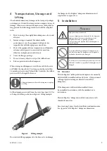
Page 9: ...rom the cover hose part 2 Use soft straps for lifting as shown in Figure 4 Lifting example Figure 4 Lifting example Do not attach lifting equipment to the bore as it can damage the dampener For Expuls...

Page 10: ...equipment 2 Apply pipe tape or hemp on the connector threads 3 Tighten the connectors between the dampener and pipeline Figure 7 Maximum dimension between the pipeline center axes Dim X 1 x DN size f...

Page 11: ...are offered as a guideline in Table 4 Schedules will vary with applications Table 4 Maintenance schedule Maintenance task Frequency advice Check the dampener pressure Every month Check the dampener d...

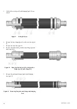
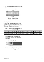
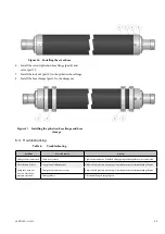
Page 12: ...part 5 on the cover hose part 2 7 Remove the cover hose part 2 8 Remove the lock nuts 9 pulsation hose flanges part 4 and o rings 10 Figure 10 Removing the lock nuts 9 pulsation hose flanges part 4 a...

Page 13: ...ghtening instructions are not given Part numbers in these assembly instructions refer to figures 1 and 2 Table 5 General tightening torques bolt class 8 8 lubrication MoS2 Size M6 M8 M10 M12 M16 M20 M...

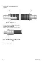
Page 14: ...rs Figure 14 Installing the o rings 3 Install one pulsation hose flange part 4 and plug part 8 to the other end of the dampener 4 Install the lock nut part9 on the pulsation hose flange Figure 15 Inst...

Page 15: ...Table 6 Troubleshooting Problem Possible reason Action Leakage from connection Connector is loose Tighten the connector If needed add pipe tape or hemp fiber to the connection Hose lifetime is short O...

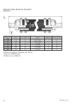
Page 16: ...kg Max Pressure Bar 32 1100 40 G1 1 4 Threads 7 10 40 1100 50 G1 1 2 Threads 11 10 50 1400 63 G2 Threads 13 10 65 1500 76 G2 1 2 Threads 18 10 80 1500 102 G3 Threads 38 10 100 2000 115 G4 Threads 55...

Page 17: ...17 4EXP70EN 9 2023...

Page 18: ...4EXP70EN 9 2023 18...

Page 19: ...19 4EXP70EN 9 2023...

Page 20: ...Stonel Valvcon and Flowrox and certain other trademarks are either registered trademarks or trademarks of Valmet Oyj or its subsidiaries in the United States and or in other countries Valmet Flow Con...

Reviews:

Related manuals for Flowrox Expulse Series