background image

INDICE

INDEX

1

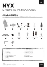
COMPONENTES
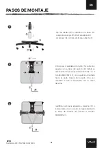
PASOS DE MONTAJE
ADVERTENCIAS

INSTRUCTION GUIDE                     ENGLISH

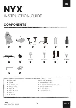
COMPONENTS
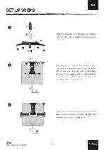
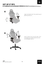
SETUP STEPS
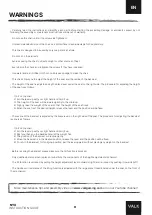
WARNINGS

MANUEL D’INSTRUCTIONS         FRANÇAIS

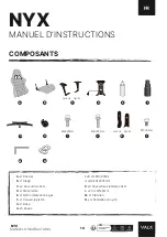
COMPOSANTS
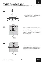
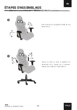
ÉTAPES D’ASSEMBLAGE
AVERTISSEMENTS

MANUALE D’ISTRUZIONI               ITALIANO
                     ITALIANO

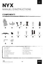
COMPONENTI
PASSI DI MONTAGGIO 
AVVERTENZE

GEBRAUCHSANWEISUNG             GERMAN
                     ITALIANO

KOMPONENTEN
MONTAGESCHRITTE 
WARNUNGEN

MANUAL DE INSTRUCCIONES    ESPAÑOL

PÁGINA

2

3-4

5

PAGE

6

7-8

9

PAGE

10

11-12

13

PAGINA

14

15-16

17

SEITE

18

19-20

21

Summary of Contents for NYX

Page 1: ...INSTRUCTION GUIDE INSTRUCTION GUIDE NYX 1 1...

Page 2: ...WELCOME TO THE RESISTANCE...

Page 3: ...UCTIONS FRAN AIS COMPOSANTS TAPES D ASSEMBLAGE AVERTISSEMENTS MANUALE D ISTRUZIONI ITALIANO ITALIANO COMPONENTI PASSI DI MONTAGGIO AVVERTENZE GEBRAUCHSANWEISUNG GERMAN ITALIANO KOMPONENTEN MONTAGESCHR...

Page 4: ...Mecanismo E x1 Pist n de elevaci n a gas F x1 Cubierta del pist n G x1 Base H x5 Ruedas I x8 Tornillos M8 20mm J x4 Tornillos M8 25mm K x2 Tapas laterales I D L x2 Tornillos M5 8mm M x1 Llave Allen N...

Page 5: ...ase del asiento B Instala el mecanismo D en la base del asiento B con 4 tornillos M8 20mm I con la palanca orientada hacia la parte trasera del asiento Una vez montada la silla la accionar s con la ma...

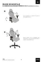
Page 6: ...a el pist n E en el alojamiento del mecanismo D y coloca las 2 tapas laterales K usando 2 tornillos M5 8mm L Fija el respaldo A al asiento B usando 4 tornillos M8 25mm J NYX L L M M K K M M J J ESP ES...

Page 7: ...ara que la altura del asiento vaya subiendo 5 Cuando el asiento est en la altura deseada suelta la palanca y la posici n quedar fija El reclinado del respaldo se regula mediante la palanca de color ne...

Page 8: ...t L R D x1 Mechanism E x1 Gas lift F x1 Gas lift cover G x1 Base H x5 Casters I x8 Screws M8 20mm J x4 Screws M8 25mm K x2 Lateral protective covers L R L x2 Screws M5 8mm M x1 Allen Wrench N x4 Nylon...

Page 9: ...les in the base of the seat B Install the mechanism D on the seat base B with 4 M8 20mm screws I with the lever facing the back of the seat Once the chair is assembled you will operate it with your ri...

Page 10: ...sert the gas lift E into the notch of the mechanism D and attach the side covers K with 2 M5X8MM screws L Attach the backrest A to the seat B using 4 M8 25mm screws J INSTRUCTION GUIDE NYX L L M M K K...

Page 11: ...aise the weight of the seat so that the height of the seat rises 5 When the seat is at the desired height release the lever and the position will be fixed The recline of the backrest is adjusted by th...

Page 12: ...ouvercle piston G x1 Base H x5 Roues I x8 Vis M8 20mm J x4 Vis M8 25mm K x2 Couvertures lat rales G D L x2 Vis M5 8mm M x1 Cl Allen N x4 Rondelles en nylon A B C D E F G H I J K L M8 20mm M8 25mm M5 8...

Page 13: ...B Installez le m canisme D sur la base du si ge B avec 4 vis M8 20mm I avec le levier tourn vers l arri re du si ge Une fois le si ge mont vous le manipulerez avec votre main droite 2 3 Identifiez le...

Page 14: ...ans le logement du m canisme D et montez les 2 couvercles lat raux K l aide de 2 vis M5 8mm L Fixez le dossier A au si ge B l aide de 4 vis M8 25mm J NYX L L M M K K M M J J ESP FR MANUEL D INSTRUCTIO...

Page 15: ...minimum 4 Soulevez l g rement le poids du si ge pour que la hauteur du si ge augmente 5 Quand le si ge est la hauteur d sir e rel chez le levier et la position sera fix e L inclinaison du dossier se...

Page 16: ...io del pistone G x1 Base H x5 Ruote I x8 Viti M8 20mm J x4 Viti M8 25mm K x2 Coperture laterali S D L x2 Viti M5 8mm M x1 Chiave a brugola N x4 Rondelle di nylon A B C D E F G H I J K L M8 20mm M8 25m...

Page 17: ...stallare il meccanismo D nella base del sedile B con 4 viti M8 20mm I con la leva rivolta verso il retro del sedile Una volta che il sedile montato lo azionerete con la mano destra 2 3 Identificare i...

Page 18: ...ll alloggiamento del meccanismo D e montare i 2 coperchi laterali K utilizzando 2 viti M5 8mm L Fissare lo schienale A al sedile B usando 4 viti M8 25mm J NYX L L M M K K M M J J ESP IT MANUALE D ISTR...

Page 19: ...del sedile per aumentarne l altezza 5 Quando il sedile all altezza desiderata rilasciare la leva e la posizione sar fissa La reclinazione dello schienale regolata per mezzo della leva nera sul lato d...

Page 20: ...x1 Sockel H x5 R der I x8 Schrauben M8 20mm J x4 Schrauben M8 25mm K x2 Seitliche Abdeckungen L R L x2 Schrauben M5 8mm M x1 Inbusschl ssel N x4 Nylon Unterlegscheibenn A B C D E F G H I J K L M8 20m...

Page 21: ...tieren Sie den Mechanismus D mit 4 Schrauben M8 20mm I an der Sitzbasis B wobei der Hebel zur R ckseite des Sitzes zeigt Sobald der Sitz montiert ist bedienen Sie ihn mit der rechten Hand 2 3 Identifi...

Page 22: ...echanikge h use D ein und montieren Sie die 2 seitlichen Abdeckungen K mit 2 Schrauben M5 8mm L Befestigen Sie die R ckenlehne A mit 4 Schrau ben M8 25 mm J am Sitz B NYX L L M M K K M M J J ESP DE GE...

Page 23: ...enkt 4 Heben Sie das Gewicht des Sitzes leicht an um die Sitzh he zu erh hen 5 Wenn sich der Sitz in der gew nschten H he befindet lassen Sie den Hebel los und die Position wird fixiert Die Neigung de...

Page 24: ...VALKGAMING COM 1 1...

Reviews: