background image

Installing the power unit

positioning
the power unit should be installed in service 
rooms such as a store-room or garage and 
protected against weather, humidity and sudden 
changes of temperature. 
the power unit is not designed for outdoor use 
unless suitably protected.
the installation place shall be sufficiently spacious 
and well lit to allow for a easy access to the 
vacuum unit.
when installed indoors or in a semi-enclosed area 
ensure the space is properly ventilated.
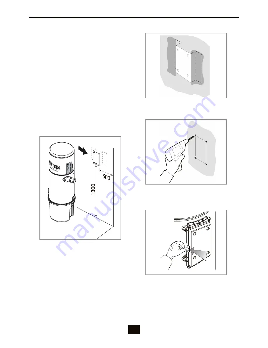
the power unit must be fixed to the wall at a 
height that allows for an easy dismantling of the 
dust container and the replacement of the filter 
cartridge.

If using a Wall Bracket

1a

. mount the bracket on the wall.

If mounting direct to the Wall

1B

. drill. using a spirit level check that the 

bracket is level

2

. release the locking lever.

Summary of Contents for V100

Page 1: ...Installation Operation Manual Premium Cyclonic Central Vacuum Systems ...

Page 2: ... No part of this publication may be reproduced transmitted or stored in a retrieval system in any form or by any means electronic mechanical photocopying recording or otherwise without the prior written permission of Ness Ness reserves the right to make changes to features and specifications at any time without prior notification in the interest of ongoing product development and improvement 2010 ...

Page 3: ...mponents 6 Installing the Power Unit 7 8 Connecting the PVC Pipe 9 Electrical 10 Start vacuuming 11 How to empty the dust container 12 How to clean the filter cartridge 13 How to replace the filter cartridge 14 Technical Specifications 15 Contents ...

Page 4: ...sed space Do not vacuum any wet surfaces Do not vacuum any liquids including any fuels Do not vacuum anything that is hot burning or smoking Do not vacuum any ash even it appears dormant Avoid vacuuming plaster dust or talcum powder which can cause clogging of the filter cartridge Do not obstruct block or impede the hose or wall valve inlets Keep hair all parts of the body and loose clothing away ...

Page 5: ...al part of the vacuum power unit and must be handed over to the user It must be kept in a safe place and consulted carefully as all of the warnings provide important instructions for safety in the phases of installation use and maintenance Responsibility The vacuum power unit must be used only for the purpose for which it has been designed Any other use is considered improper use and is therefore ...

Page 6: ...00 Fuse Power Input Low voltage switch input Sound proof motor compartment Air Exhaust Wall bracket Air intakes x 2 for left or right hand installation Dust container hinges Filter cartridge Dust cone Dust container ...

Page 7: ...ufficiently spacious and well lit to allow for a easy access to the vacuum unit When installed indoors or in a semi enclosed area ensure the space is properly ventilated The power unit must be fixed to the wall at a height that allows for an easy dismantling of the dust container and the replacement of the filter cartridge If Using a Wall Bracket 1A Mount the bracket on the wall If Mounting Direct...

Page 8: ...s to the support 5A If using a wall bracket Fix the support to the wall bracket 5B If mounting directly to the wall Screw the support to the wall 6 Remove the dust container 7 Secure the Power Unit to the support 8 Make sure the locking lever locks into position 9 Attach the dust container ...

Page 9: ...th natural exhaust Suitable for outdoor undercover installations Exhaust o Air intakes Two air intakes are provided for left or right hand pipe entry The unused intake must blocked with the cap provided Air intakes Two air intakes are provided for left or right hand pipe entry The unused intake must blocked with the cap provided Exhaust Optional muffler ...

Page 10: ...ble to an incorrect electrical connection Danger Do not touch the power unit with wet or damp hands Keep non authorised people and children clear of the power unit Mains socket Fuse LED Power ON LED Unit Running Low voltage switch input Low voltage wiring to inlet valves Standard 10A mains power point Once the power unit has been connected to the mains check all vacuum sockets using the flexible h...

Page 11: ... guides on the inlet valve To start insert the hose into one of your inlet valves Align the locating tab on the hose cuff with the two guides on the inlet valve If the hose is inserted correctly the power unit will not start until you turn it on using the switch on the hose handle To stop turn off using the switch on the hose handle then unplug the hose from the inlet valve Switch Hose operation O...

Page 12: ...ks or blockages 1 Remove the dust container 3 Empty the dust container 2 Lift out the Dust Cone 4 Replace the cone ensuring it is pointing downwards and reassemble the dust container paying attention to the seal position Do not operate the power unit without a filter cartridge Not observing this precaution may result in serious damage to the motor and will void the manufacturer s warranty Please w...

Page 13: ...ck the filter cartridge at least every 4 months Remove the filter cartridge and wash it with tap water During washing pay attention not to damage the filter material If the filter is damaged during cleaning the cartridge must be replaced After washing allow the cartridge to dry Do not expose it to strong heat sources Do not operate the power unit without a filter cartridge Not observing this preca...

Page 14: ...system is used Turn off the mains power at the power point 1 Remove the dust container 3 Insert the new cartridge and tighten the retaining nut by turning the cartridge until it fits snugly in place 2 Loosen the retaining nut and remove the old cartridge 4 Replace the cone ensuring it is pointing downwards and reassemble the dust container paying attention to the seal position 14 ...

Page 15: ...Vacuum socket voltage 12 V Air flow 180 m h Max vacuum 2 879 mmH 2 O Filtering surface 0 4 m2 Filter cartridge material Polyester Dust container capacity 15 litres Height 580 mm 900 mm Diameter 280 mm Weight 13 kg 16 kg Construction Body Metal Collection container Plastic 900 280 580 280 Technical 15 ...

Page 16: ......

Reviews: