- 37 -
after maintain.
H Forbid insert any tools into fan fence of unit, fan is dangerous. (child special care)
I Don’t use the unit if turn off the fan fence.
J To avoid electric shock or cause fire, don’t store and use fixture, oil paint and petrol etc.
combustible gas or liquid around the unit; don’t throw the water or other liquid on the unit and
don’t touch the unit by wet hand.
K
Don’t adjust the switch, valve, controller and internal data except company server or
authorized staff.
L If safety protection device often start up, please contact factory or local dealer.
Section 4
General maintenance
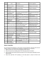
Controller Error Codes
◎
If there’s error in the heat pumps, the error code and error definition will be
displayed in the main interface, and saved the record in FAULTY column inside the
SETTING interface.
◎
The following Common Error Codes will be displayed on the controller panel:
Error Code
Definition of Error or Protection
Er 03
Water flow failure
Er 04
Antifreeze in winter
Er 05
High pressure fault
Er 06
Low pressure fault
Er 09
Communication failure
Er 10
Communication failure of frequency conversion module (alarm when
communication between outer board and drive board is
disconnected)
Er 12
Exhaust temp too high protection
Er 14
Water tank temp. sensor fault
Er 15
Water inlet temp. sensor fault
Er 16
Evaporator coil temp. sensor fault
Er 18
Exhaust temp. fault
Er 20
Abnormal protection of frequency conversion module
Er 21
Ambient temp. sensor fault
Er 23
Cooling outlet water temp. supercooling protection
Er 26
Heat sink temp. fault
Er 27
Outlet water temp. sensor fault
Er 29
Return gas temp. sensor fault
Er 32
Heating too high outlet water temp. protection
Er 33
Coil temp. too high
Summary of Contents for V1 Series
Page 9: ...8 V1 18 V1 23 V1 28 V1 35...
Page 10: ...9 Exploded view V1 08...
Page 11: ...10 V1 13...
Page 12: ...11 V1 18 23...
Page 13: ...12 V1 28 35...
Page 16: ...15 Figure 2 Figure 3...
Page 18: ...17 Figure 7 Figure 8...
Page 20: ...19 Figure 11 Figure 12 Figure 13...
Page 23: ...22 Electrical Wiring Diagram 1 Single phase system V1 08...
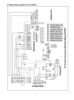
Page 24: ...23 2 Three phase system V1 13 18 23...


