Valcom V-2928 User Manual Download Page 1


   Issue 

5


947150 


TALKBACK INTERCOM SYSTEM 
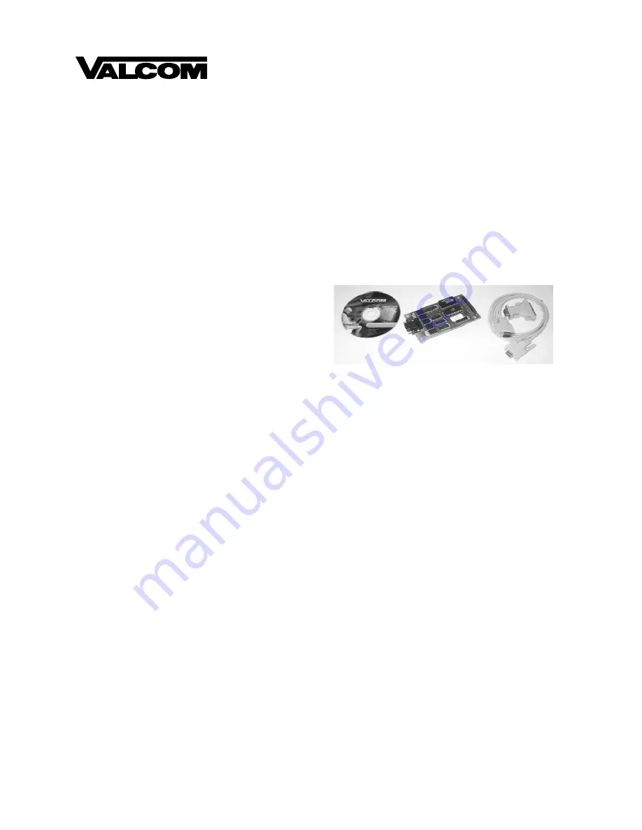
V-2928 OPTION BOARD 


The V-2928 Option Board is an add-on feature for the V-2924A Expandable Zone Talkback Intercom 
System.  The addition of this board provides the following supplemental features: 


Time sync output 


Custom page groups 

 Enhanced 

Caller 

ID 


Flexible Architectural numbering plan 


Interface to the PC Programming Tool 


Store user data to EEROM 


Real time clock for SMDR printer 


Auto detect for Com Port or Modem 


Evacuation tone to specified groups 


Time tones to any of the Pre-Determined 
Groups selected 


Read software/firmware revision numbers 

Dimensions/Weight 


5.3" L x 3.00" W x 1.10" D 


(13.46cm L x 7.62cm W x 2.79cm D)


0.9 lbs (0.41 kg) 


The V-2924A Programming Tool is a windows based 
software tool designed to interface with the V-2928 
Option Board.  The Option Board and the Programming Tool must both be installed to access the 
additional features provided by the Option Board.  

All features must be set with the Programming Tool 

when the Option Board and Programming Tool are installed. 


CONTENTS


INSTALLATION OF THE OPTION BOARD


  2 

INSTALLATION OF THE PROGRAMMING TOOL


  2 


Figure 1 - Option Board Location on the Control Board 

  3 

USING THE PROGRAMMING TOOL


  4 


System Configuration 

  4,5 


Architectural Number and CLID Programming 

  6,7 


Audio Connection 

  7,8 


Class of Service 

  8 


Clock


Custom Page Groups 

  10 


Master Clock Schedule 

11,12 

 System 

13,14 


Save Programmed Data to File 

14 

COMMUNICATING WITH THE V-2924A

 15 

 Initiating 

Communications 

15 


Direct Connect, Modem Connect 

15 


Select Dialing Method 


Modem Connect, Manual Connect 

15,16 


Send Data to V-2924A/Receive Data from V-2924A 

16,17 


Set System Date and Time 

17 


Read Software and Firmware Revision Number 

17 

 Ending 

Communications 

17 

SETUP OF THE V-2924A MODEM

 18-21 

MENU OPTIONS

 21-23 


Print, Window, Help, Exit


TECHNICAL ASSISTANCE, WARRANTY

 23


ADDITIONAL HARDWARE CONNECTIONS

 24


Summary of Contents for V-2928

Page 1: ...g Tool must both be installed to access the additional features provided by the Option Board All features must be set with the Programming Tool when the Option Board and Programming Tool are installed...

Page 2: ...2928 Option Board requires the use of the PC Programming Tool to access the various features it provides INSTALLATION OF THE PROGRAMMING TOOL Minimum Computer Requirements for the Valcom V 2924A Progr...

Page 3: ...directly over JP2 on the Control Board Press Option Board firmly into place FIGURE 1 OPTION BOARD LOCATION ON THE V 2928 CONTROL BOARD Side View Top View P10 P1 RS232 Serial Port for SMDR DB9 Connecto...

Page 4: ...is being created Click on New from the pull down menu A System Configuration screen is displayed to allow selection of the installed components within the system Select one of the following from the...

Page 5: ...e Programming Window allows each option to be accessed by selecting the option and pressing Open or by double clicking on the selected option All functions can be listed at once by pressing Open All A...

Page 6: ...part of the system The Edit Station Entry allows a CLID description to be entered for each station Example 105 would be the Arch and MR HALL would be the CLID description 15 character limit The Delete...

Page 7: ...23 24 Main Board Group 5 Stations 25 26 27 28 29 30 Expansion 1 Group 6 Stations 31 32 33 34 35 36 Expansion 1 Group 7 Stations 37 38 39 40 41 42 Expansion 1 Group 8 Stations 43 44 45 46 47 48 Expansi...

Page 8: ...ue as they are made 1 button press from the station the call is received as a normal call 4 button presses from the station the call is received as an emergency call Normal Only Calls from stations pr...

Page 9: ...t When Clock is selected the following screen is displayed Click on the tab for Clock A Then click on the down arrow next to Clock Type and select the clock type code codes are defined in the V 2927 m...

Page 10: ...Select the Page Groups to receive custom paging by clicking on the desired box Each Custom Page Group can contain all groups or a combination of groups Example Custom Page Group 50 could contain page...

Page 11: ...be distributed between schedules Dial codes may be used to force a schedule or to turn a schedule off 94X forces schedule on with the X being the number of the schedule i e 941 will force Schedule 1...

Page 12: ...osure Select which Page Group s tone should go to Select Save NOTE The contact closure pairs 13 14 15 16 on the system punchdown block should be wired to the tone select input of an external tone gene...

Page 13: ...lected Select the desired options and click on OK to exit this screen The options are described in more detail in the Control Unit V 2924A document or select Help from the pull down menu for on screen...

Page 14: ...nt of programmed options Save Programmed Data to a File When the programming selections are complete click on the File menu option to access the pull down menu and select Save Define file name and loc...

Page 15: ...t page 16 REMINDER For a modem to communicate with the V 2924A there must be a remote modem connected to the V 2924A See page 18 for Setup of the Remote Modem Serial Port The serial port on the V 2928...

Page 16: ...Connect From the Programming Tool select File Modem and Manual Connect Follow the instructions as described on the screen Messages should be displayed stating Initializing Dialing and Modem Connectio...

Page 17: ...Press Update to set the new Date Time or Cancel to leave unchanged The Automatic DST Adjustment can be enabled or disabled here The DST correction is based on the pre 2007 rules first Sunday of April...

Page 18: ...ME PROCEDURE THAT SHOULD BE PERFORMED WHEN THE MODEM IS INSTALLED Select Communications Setup from the File Menu as shown in the following screen display 2 Select Remote Modem Setup and the following...

Page 19: ...een to be displayed requests selection of a COM Port Select the proper COM Port and click OK The program then attempts to test the communication line between the PC and the modem If the connection is...

Page 20: ...e default modem commands for the US Robotics Sportster appear below Click on Enter to send these commands to the modem 7 Save the settings to the modem s memory by selecting Yes as shown in the figure...

Page 21: ...t Codes SW3 Suppress Result Codes SW4 Echo Offline Commands SW5 Auto Answer on Ring SW6 Carrier Detect Normal SW7 Load NVRAM Defaults on Power up SW8 Smart Mode 9 After modem setup is complete the scr...

Page 22: ...ral screens to be closed at once Instead of going through several open screens closing them individually select Window Close All or select the screens individually from the pull down window HELP The H...

Page 23: ...23...

Page 24: ...inal shipment 3 the product has not been altered in any way or repaired by others and that factory sealed units are unopened a service charge plus parts and labor will be applied to units defaced or p...

Page 25: ...POWER SUPPLY 24VDC Available only with Options Card Installed AC GND 26 WH BL 1 BL WH 27 WH O 2 O WH 28 WH GR 3 GR W 29 W BR 4 BR W 30 W S 5 S W 31 R BL 6 BL R 32 R O 7 O R 33 R G 8 G R 34 R BR 9 BR R...

Reviews: