


Split Type Installation Manual
6
3
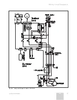
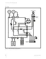
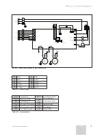
Connecting Diagram
Fig. 3.1 Connection.
3.1
Electric Characteristics
V 12-025 W
V 12-035 W
V 12-050 W
V 12-060 W
Power supply (V/Ph/Hz)
230/1/50
230/1/50
230/1/50
230/1/50
S
upply
Recommended minimum supply section up to 25 meters (mm
2
)
1,5
1,5
2,5
2,5
Indoor / Outdoor
Indoor
Indoor
Indoor
Indoor
Thermal-magnetic circuit breaker, type D (A)
10
10
16
16
Recommended minimum interconnection section up to 25 meters (mm
2
)
1,5
1,5
2,5
2,5
Inteconnect shielded cable or not (YES / NO)
NO
NO
NO
NO
Inmediatte residual current protector (A)
0,03
0,03
0,03
0,03
V 12-060 M2W
Power supply (V/Ph/Hz)
230/1/50
S
upply
Supply section up to 25 meter (in mm
2
)
2,5
Indoor / Outdoor
Outdoor
Thermal-magnetic circuit breaker, type D (A)
16
S
upply
Supply section up to 25 m (in mm
2
)
1,5
Indoor/Outdoor
Indoor
Thermal-magnetic circuit breaker, type D (A)
10
Interconnection section up to 25 meter (mm
2
)
1,5
Inteconnect Shield or not (YES/NO)
NO
Immediatte residual current protector (A)
0,03
Table 3.1 Electric Characteristics.
3 Connecting Diagram
Summary of Contents for V 12-025 HWI
Page 30: ...Split Type Installation Manual 30 8 Photographs 8 5 Compresor 050 W 8 6 Compresor 065 W...
Page 31: ...Split Type Installation Manual 31 EN Photographs 8 8 7 PCB 025 035 MULTI...
Page 32: ...Split Type Installation Manual 32 8 Photographs 8 8 PCB 025 035W MONO...
Page 33: ...Split Type Installation Manual 33 EN Photographs 8 8 9 PCB 050 065W MONO...
Page 34: ...Split Type Installation Manual 34 8 Photographs 8 10 PCB OUTDOOR MULTI...