


5
5
1021
880
95.5
480
120
max. 995*
max. 995 *
1a
1a
190
1b
2
7 6 5 4 3 8
35
50
380
120
GW 547/1
fig. 1
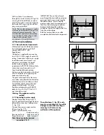
2.3 Boiler connections
1 Compression union (flow of
heating system)
2 Service valve (flow of heating
system)
3 Domestic hot water connection
4 Compression Union (gas)
5 Gas service valve (supplied with
the boiler)
6 Cold water connection with
shut-off valve
7 Service valve (return of heating
system)
8 Compression union (return of
heating system)
9 Pressure relief valve
200
124
50
35
70
25
1
2
3 4 5 6 7 8 9
GW 546/1
fig. 2
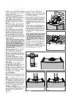
2.2 Dimensions
(All dimensions in mm)
1a Air/flue duct to the rear
1b Air/flue duct to the side
2 Appliance bracket
3 Heating system return (22 mm)
4 Cold water connection (15 mm)
5 Gas connection (15 mm)
6 Hot water connection (15 mm)
7 Heating system flow (22 mm)
8 Pressure relief valve outlet
(
3
/
4
in BSP)
* with standard horizontal flue
accessory.
(max. = 2965 mm with extensions)


